
Oil feeding system of engine

Inactive Publication Date: 2006-11-23
KAWASAKI HEAVY IND LTD
View PDF23 Cites 21 Cited by
  • Summary
  • Abstract
  • Description
  • Claims
  • Application Information

AI Technical Summary

Benefits of technology

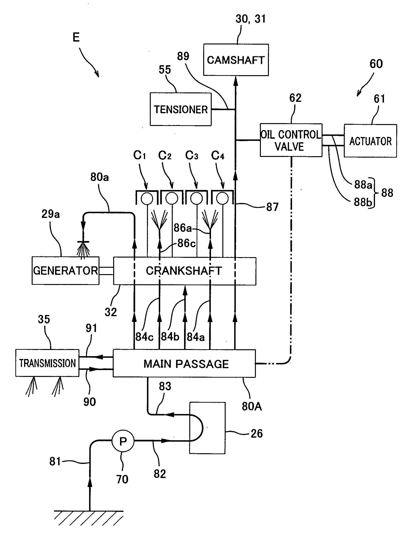
[0012] With the above mentioned configuration, when the engine speed of the engine is high, a sufficient flow rate of the oil can be obtained. Therefore, the oil can be delivered in a sufficient amount to the transmission and a pressure of the oil required to drive the portions other than the transmission can be obtained. On the other hand, when the engine speed is low, the oil control portion reduces the flow rate of the oil in the transmission oil passage, and the pressure of the oil required to drive the portions other than the transmission can be obtained.
[0013] The oil control portion may be configured to restrict the flow rate of the oil in the transmission oil passage when the pressure of the oil in the transmission oil passage is a predetermined value or less. With such a configuration, when the engine speed is high and the pressure of the oil is higher than the predetermined value, the oil pressure required to drive the portions other than the transmission can be obtained, and the oil can be fed in a sufficient amount to the transmission through the transmission oil passage. On the other hand, when the engine speed is low and the pressure of the oil is the predetermined value or less, the oil control portion restricts (or reduces) the flow rate of the oil in the transmission oil passage so that the oil is fed in a required amount to the transmission and the oil pressure required to drive the portions other than the transmission can be obtained.
[0016] The first oil passage of the transmission oil passage may be partially provided with a restricting portion having a passage with a diameter smaller than a diameter of a region in the vicinity of the restricting portion. With such a configuration, with the engine running at a low engine speed, the flow rate of the oil flowing in the transmission oil passage can be restricted, and the pressure of the oil delivered to the portions other than the transmission can be increased.
[0020] With the above mentioned configuration, the first oil pump, which is adapted to suitably feed the oil to the transmission, and the second oil pump, which is adapted to suitably feed the oil to the portions other than the transmission, can be used together. By using the second oil pump, the required oil pressure can be obtained with the engine running at a low engine speed. If the engine equipped with the second oil pump runs at a high engine speed, the pressure of the oil flowing in the engine body oil passage tends to become high up to an undesired level, and the oil tends to be delivered in excess amount. When the pressure of the oil becomes a predetermined value, the valve is opened, causing a surplus of the oil in the engine body oil passage to flow into the transmission oil passage through the bypass passage to be fed to the transmission. Because of the second oil pump, the volume of the first oil pump can be made small.

Problems solved by technology

Since the oil pump is driven in synchronization with the engine speed of the engine, oil pressure tends to become high when the engine is running at a high engine speed, and tends to become low when the engine is running at a low engine speed.
However, it may sometimes be difficult to obtain such a high oil pressure with the engine running at a low engine speed.
In order to solve this, a volume of the oil pump may be increased, which undesirably causes a substantial weight increase and a large friction loss in the engine.

Method used


Image

  • Oil feeding system of engine
  • Oil feeding system of engine
  • Oil feeding system of engine

Examples


Embodiment Construction

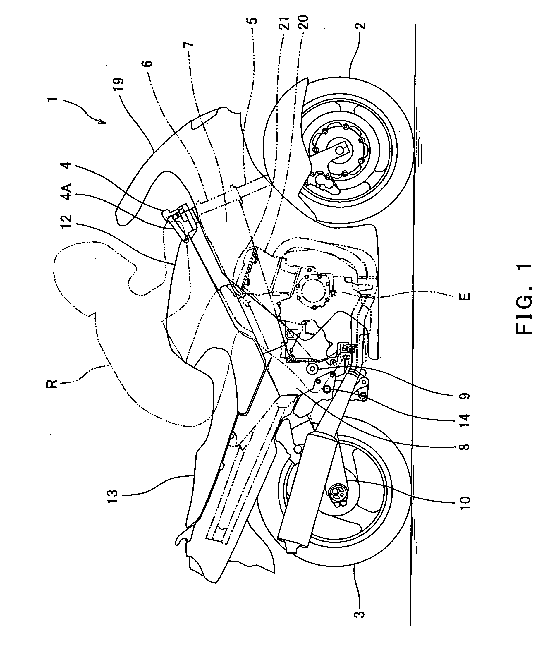
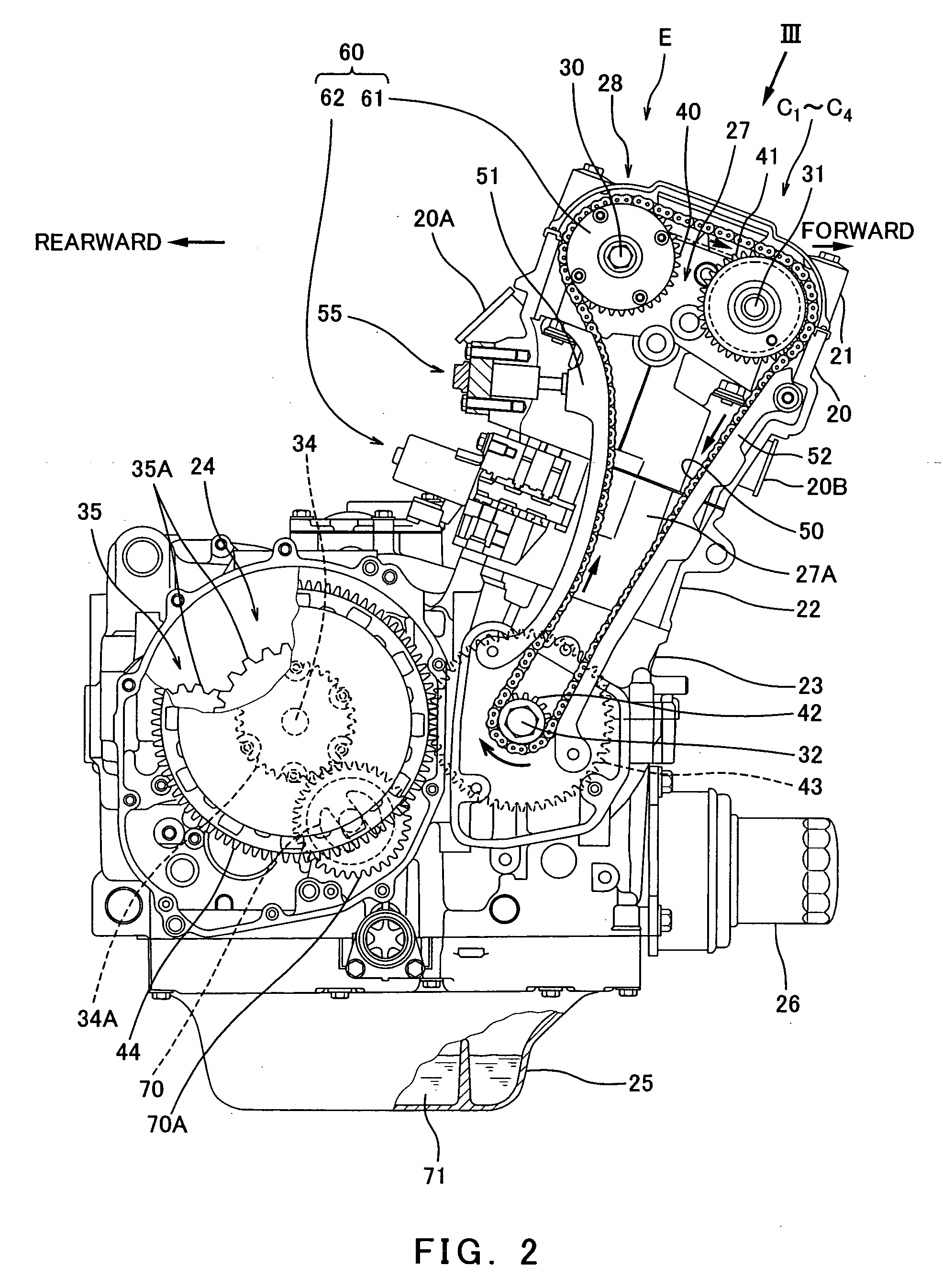
[0034] Hereinafter, an embodiment of an oil feeding system of an engine of the present invention will be described with reference to the accompanying drawings. FIG. 1 is a right side view of a motorcycle 1 in which an engine E according to an embodiment of the present invention is mounted. The motorcycle 1 is a road sport type motorcycle in which a rider R rides with an upper body leaning forward. Herein, directions are generally referenced from the perspective of the rider R mounting the motorcycle 1 of FIG. 1.

[0035] Turning now to FIG. 1, the motorcycle 1 includes a front wheel 2 and a rear wheel 3. The front wheel 2 is rotatably mounted to a lower region of a front fork 5 extending substantially vertically. A bar-type steering handle 4 is attached to an upper region of the front fork 5. The front fork 5 is mounted to a steering shaft (not shown) extending in parallel with the front fork 5. The steering shaft is rotatably supported by a head pipe 6. When the rider R rotates the s...


PUM


Abstract

An oil feeding system of an engine equipped with a transmission configured to change a rotational speed of rotation of a crankshaft and to output the rotation, including an oil pump configured to be driven in cooperation with the rotation of the crankshaft, an oil passage through which the oil outflowing from the oil pump flows, in which the oil passage includes a transmission oil passage through which the oil outflowing from the oil pump is guided to the transmission, and an engine body oil passage through which the oil outflowing from the oil pump is guided to portions other than the transmission, and an oil control portion configured to change a ratio between a pressure of the oil flowing through the transmission oil passage and a pressure of the oil flowing through the engine body oil passage.

Description

TECHNICAL FIELD [0001] The present invention generally relates to an oil feeding system of an engine configured to be integral with a transmission. More particularly, the present invention relates to an oil feeding system of an engine that is suitable for use with a motorcycle and is configured to feed oil to a transmission and components other than the transmission. BACKGROUND ART [0002] Some engines mounted in vehicles such as motorcycles or all terrain vehicles (ATVs) are integral with transmissions. In such engines, an oil pump is driven in synchronization with an engine speed of the engine to suction up oil from an interior of an oil pan mounted at a bottom portion of the engine or from an oil tank externally mounted to the engine, thus delivering the oil to the transmission and engine components. [0003] To be specific, the oil outflows from the oil pump and is delivered, through an oil passage formed in an interior of the engine, to the transmission to lubricate and cool the t...

Claims


Application Information

Patent Timeline
IPC IPC(8): F01M1/04F01M1/02F01M1/06F01M1/16F16H57/04
CPCF01M1/02F01M1/16F16H57/0456F02B61/02F01M9/108
Inventor SUZUKI, KOZOFUKAMI, YOJINONAKA, YOSUKE
Owner KAWASAKI HEAVY IND LTD
Learn More