Radio frequency power amplifier

a power amplifier and radio frequency technology, applied in amplifiers, amplifiers with semiconductor devices only, amplifiers with semiconductor devices, etc., can solve the problems of destroying devices, thermal runaway, and the resistance values of resistors rab>101/b> through rab>10/b>, and achieve superb radio frequency characteristics and sufficient destruction resistance.

Inactive Publication Date: 2006-11-23
COLLABO INNOVATIONS INC
View PDF7 Cites 3 Cited by
  • Summary
  • Abstract
  • Description
  • Claims
  • Application Information

AI Technical Summary

Benefits of technology

[0009] Therefore, an object of the present invention is to provide a radio frequency power amplifier providing both of a sufficient destruction resistance and superb radio frequency characteristics.

Problems solved by technology

A specific transistor having a high temperature may cause thermal runaway due to excessive heat generation during operation and destroy the device due to an increase in the base current.
However, the resistance values of the resistors Ra101 through Ra10n cannot be very large because excessively large resistance values of the resistors Ra101 through Ra10n decrease a power gain of a radio frequency signal.
It is very difficult to improve both.

Method used


Image

  • Radio frequency power amplifier
  • Radio frequency power amplifier
  • Radio frequency power amplifier

Examples


first embodiment

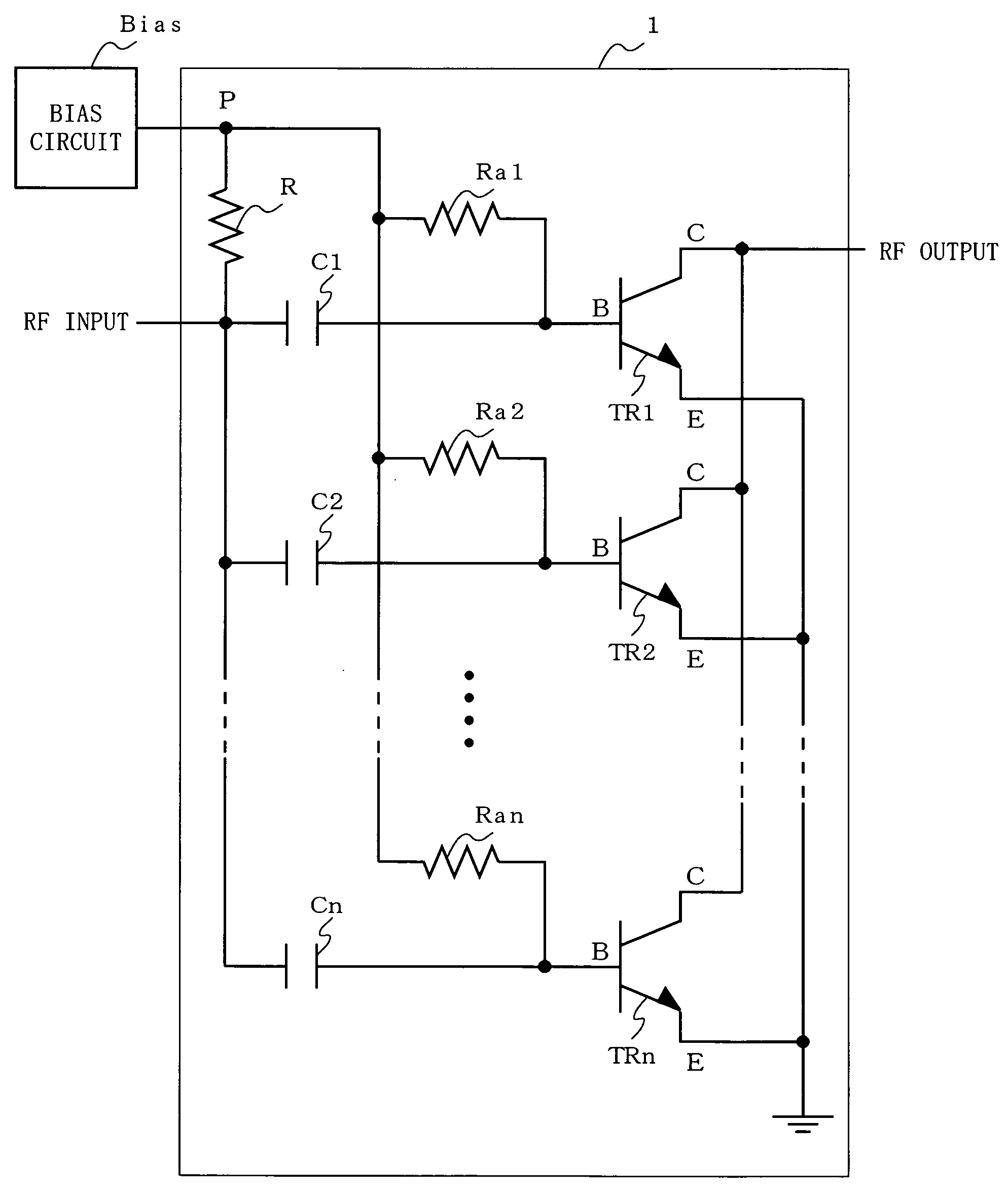
[0027]FIG. 1 shows a circuit configuration of a radio frequency power amplifier 1 according to a first embodiment of the present invention. As shown in FIG. 1, the radio frequency power amplifier 1 according to the first embodiment includes transistors TR1 through TRn, capacitors C1 through Cn, resistors Ra1 through Ran, and a bridge resistor R. Herein, n is an integer equal to or greater than two. As the transistors TR1 through TRn, hetero-junction bipolar transistors using a compound semiconductor (InGaP) or other types of transistors using Si or SiGe are usable.

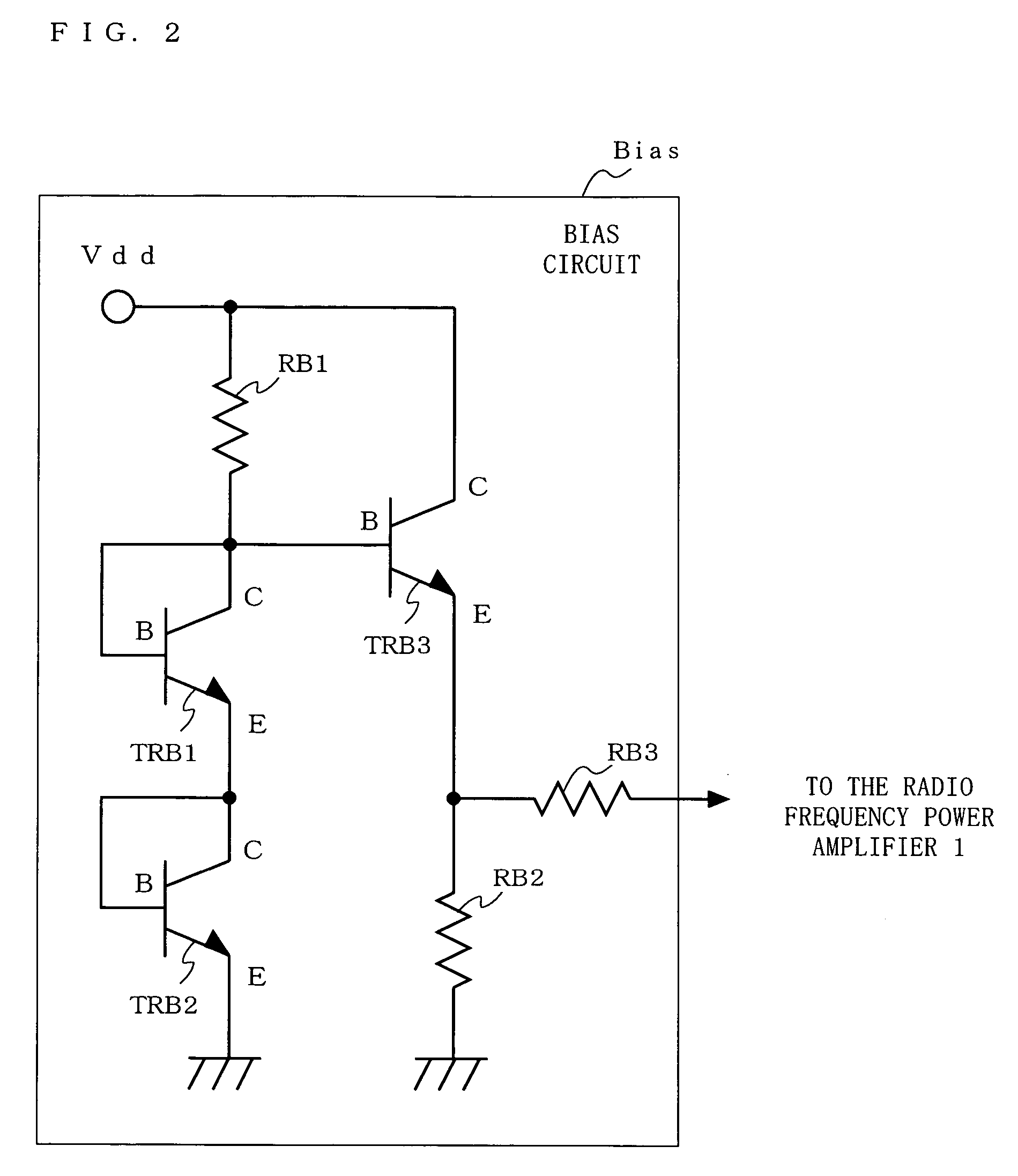
[0028] A radio frequency signal (RF), which is an AC signal, is input to a base (B) of each of the transistors TR1 through TRn via the corresponding capacitor among the capacitors C1 through Cn, is amplified, and is output from a collector (C) of each of the transistors TR1 through TRn. An emitter (E) of each of the transistors TR1 through TRn is grounded. A direct current bias voltage (DC) given from a bias circuit (Bias...

second embodiment

[0038]FIG. 6 shows a circuit configuration of a radio frequency power amplifier 2 according to a second embodiment of the present invention. As shown in FIG. 6, the radio frequency power amplifier 2 according to the second embodiment includes transistors TR1 through TRn, capacitors C1 through Cn, resistors Ra1 through Ran, resistors Rb1 through Rbn, and a bridge resistor R. As can be appreciated from FIG. 6, the radio frequency power amplifier 2 according to the second embodiment includes the resistors Rb1 through Rbn in addition to the structure of the radio frequency power amplifier 1 according to the first embodiment.

[0039] The resistors Rb1 through Rbn each have a very small resistance value, and respectively inserted between a connection point of the corresponding capacitor among the capacitors C1 through Cn and the corresponding resistor among the resistances Ra1 through Ran, and the base of the corresponding transistor among the transistors TR1 through TRn. Thus, the resisto...

third embodiment

[0041]FIG. 7 shows a circuit configuration of a radio frequency power amplifier 3 according to a third embodiment of the present invention. As shown in FIG. 7, the radio frequency power amplifier 3 according to the third embodiment includes transistors TR1 through TRn, capacitors C1 through Cn, resistors Ra1 through Ran, resistors Rc1 through Rcn, and a bridge resistor R. As can be appreciated from FIG. 7, the radio frequency power amplifier 3 according to the third embodiment includes the resistors Rc1 through Rcn in addition to the structure of the radio frequency power amplifier 1 according to the first embodiment.

[0042] The resistors Rc1 through Rcn each have a very small resistance value, and inserted between the corresponding capacitor among the capacitors C1 through Cn, and a connection point of the corresponding resistor among the resistors Ra1 through Ran and the base of the corresponding transistor among the transistors TR1 through TRn. Thus, the resistors Rc1 through Rcn...


PUM


Abstract

A radio frequency signal RF is input to a base of each of transistors TR1 through TRn via a corresponding capacitor among capacitors C1 through Cn, is amplified, and is output from a collector of each of the transistors TR1 through TRn. An emitter of each of the transistors TR1 through TRn is grounded. A bias voltage DC given from a bias circuit Bias is supplied to the base of each of the transistors TR1 through TRn via a corresponding resistor among resistors Ra1 through Ran. A signal line for the bias voltage DC is connected to an input line for the radio frequency signal RF via the bridge resistor R in a direct current manner.

Description

BACKGROUND OF THE INVENTION [0001] 1. Field of the Invention [0002] The present invention relates to a radio frequency power amplifier suitable for power amplification of a radio frequency signal. [0003] 2. Description of the Background Art [0004] An amplifier used for a wireless communication device such as a mobile phone or the like generally uses a structure in which a plurality of, for example, two or three, compound semiconductor transistors for radio frequency amplification are connected to each other. As such a compound semiconductor transistor, a hetero-junction bipolar transistor has mainly been used recently for the reason regarding the single positive power source operation or the like. A final-stage amplifier for a mobile phone having an output power of about 1 to 3 W is provided by connecting a plurality of transistors in parallel to combine the outputs from the transistors, in order to obtain radio frequency characteristics and a high output. FIG. 10 shows an example o...

Claims


Application Information

Patent Timeline
Patent Type & Authority Applications(United States)
IPC IPC(8): H03F3/68
CPCH03F1/30H03F2203/21178H03F3/20H03F3/189
Inventor ENOMOTO, SHINGOINAMORI, MASAHIKOKOIZUMI, HARUHIKOTATEOKA, KAZUKIMAKIHARA, HIROKAZUMATUDA, SHINGOKAWASHIMA, KATUHIKO
Owner COLLABO INNOVATIONS INC
Why Eureka
Try Eureka