Methods and apparatus for automotive radar sensors

Inactive Publication Date: 2006-11-23
CLARIANT TECH
View PDF2 Cites 140 Cited by
  • Summary
  • Abstract
  • Description
  • Claims
  • Application Information

AI Technical Summary

Benefits of technology

[0011] Methods and apparatus are presented that reduce the overall system cost for automotive radar sensing applications through reduction of the number of the radar sensors required. In accordance with aspects of the present invention, one way sensor count reduction can be achieved is through the combination of target range, direction, and velocity determination capability with wide angular field of view coverage within a single sensor unit. One embodiment c

Problems solved by technology

Similarly, for vehicle applications requiring less than four-quadrant coverage, fewer sensors can be used, resulting in a lower system cost.
However, high range resolution capable short-range radar sensors transmit power is limited to a very low power spectral density due to the legislative requirements in the permissible spectral bands of operation, such as at or around an operation frequency of 24 GHz.
However, the w

Method used


Image

  • Methods and apparatus for automotive radar sensors
  • Methods and apparatus for automotive radar sensors
  • Methods and apparatus for automotive radar sensors

Examples


Embodiment Construction

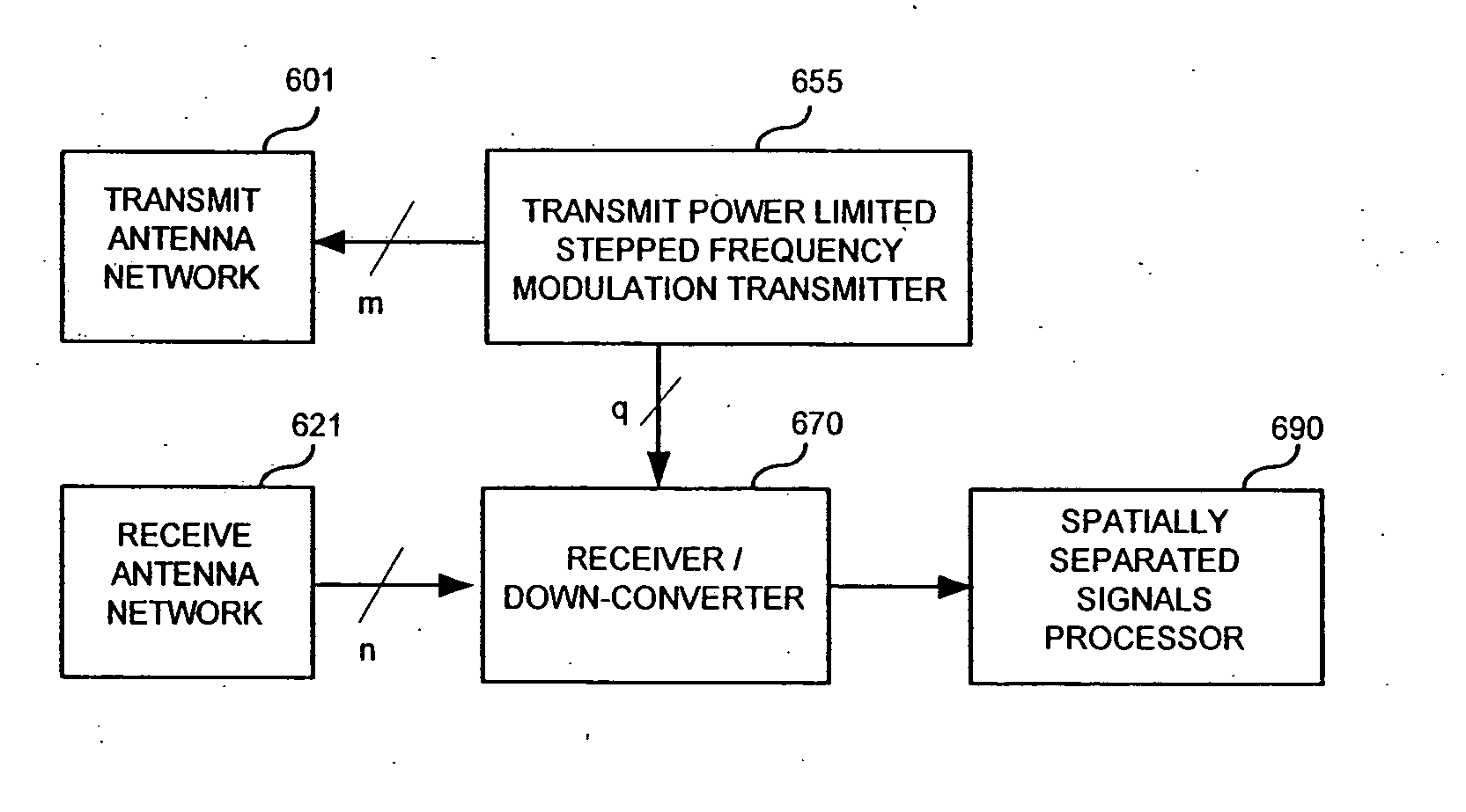
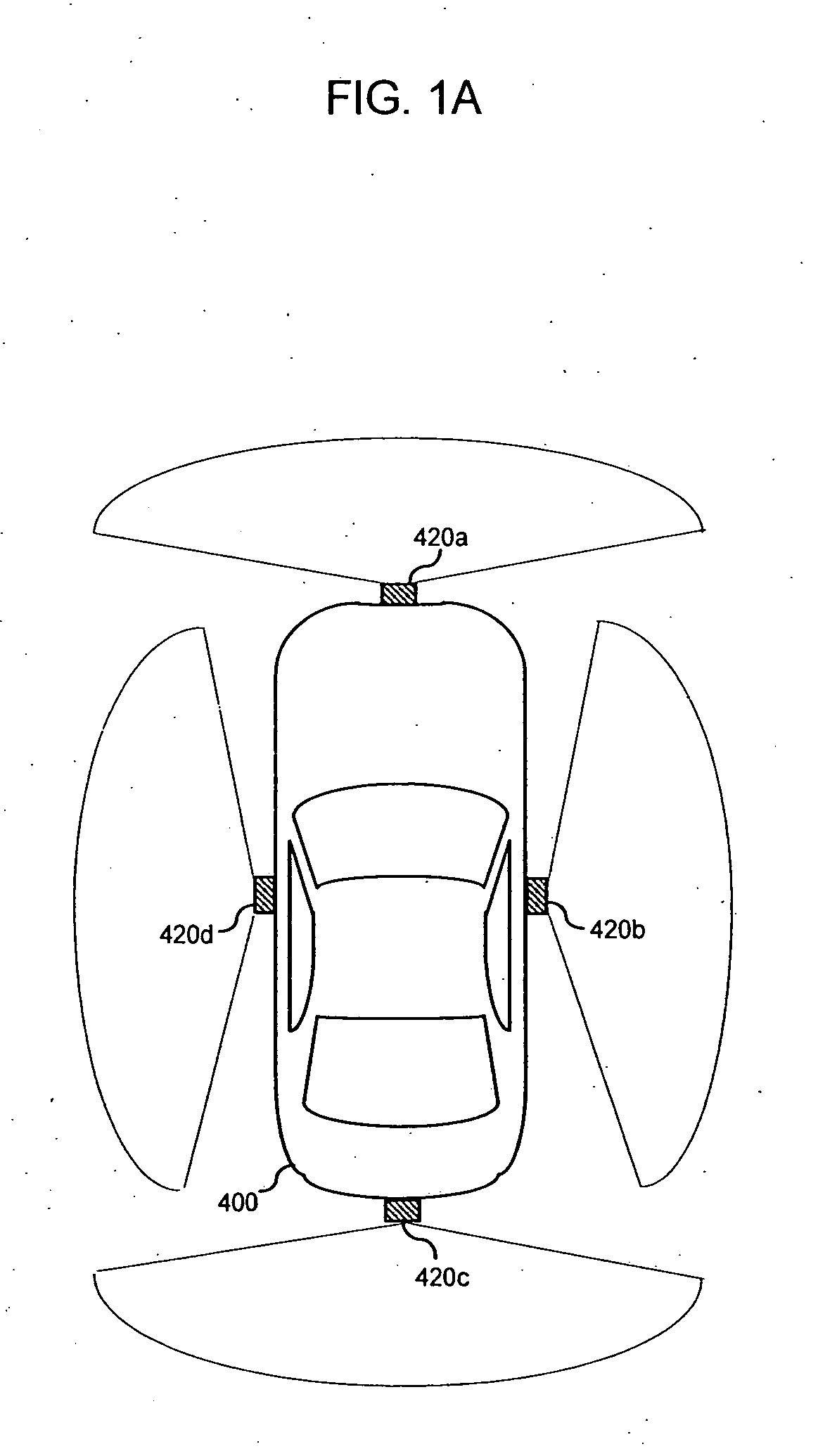
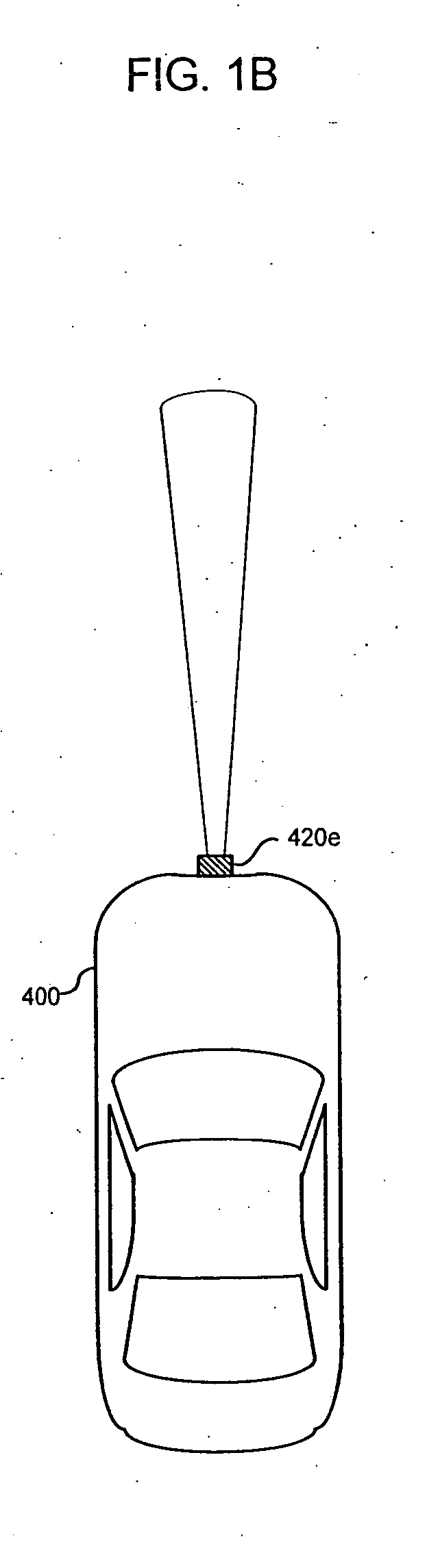
[0079] In the detailed descriptions and figures that follow, FIGS. 2A-B, 3A-F, 4A-B, 5A-C, 6A-D, 7, 8A-G, 9A-H, 11, 12, 13A-H, 14A-C, 15A-C, 16, 17A-B, 18A-B, 19, and 20A-B disclose stepped-frequency and / or stepped-PRI radar sensor architectures and methods for target range and / or velocity determination compatible with techniques of processing of spatially separated signals for target angular direction determination and / or multiple target angular discrimination, and FIGS. 10A-G illustrate examples of spatially separated signal processing techniques for target angular direction determination and / or multiple target angular discrimination. These figures and architectures are meant as examples, but not limitations, as additional methods can be used to create spatially separated signals compatible with the stepped waveforms and angular direction determination methods presented.

[0080] The spatially separated signals can be received using the different receiver methods described to provid...


PUM


Abstract

Methods and apparatus are presented that reduce the overall system cost for automotive radar sensing applications through reduction of the number of the radar sensors required. In accordance with aspects of the present invention, one way sensor count reduction can be achieved is through the combination of target range, direction, and velocity determination capability with wide angular field of view coverage within a single sensor unit. One embodiment combines a transmit-pulsed, linearly stepped frequency modulated, transmit power limited radar architecture with a spatially separated receiver antenna array, intermediate frequency down-conversion, and a digital multi-zone monopulse (DMM) signal processing technique for high-resolution target range, velocity, and azimuth angle determination and fast update rate capability in a low cost, mass-production-capable design.

Description

PRIORITY CLAIM [0001] Priority is claimed to U.S. Provisional Application 60 / 703,150 filed Jul. 27, 2005. This is a continuation-in-part application of U.S. Ser. No. 11 / 036,318 filed Jan. 14, 2005, which claims priority to and incorporates by reference U.S. provisional application 60 / 537,287, filed Jan. 16, 2004.BACKGROUND OF THE INVENTION [0002] 1. Technical Field of the Invention [0003] The subject matter disclosed generally relates to the field of automotive electronic systems and methods. More specifically, the subject matter disclosed relates to radar sensor arrangements that allow cost reduction and increased utility for automotive radar collision avoidance and driver aid applications. [0004] 2. Background of Related Art [0005] To facilitate mass deployment of automotive radar sensors, reducing the total system cost per vehicle without compromising the capability, performance, or reliability of the system is desirable. Automotive short-range sensing applications typically aim ...

Claims


Application Information

Patent Timeline
IPC IPC(8): G01S13/93G01S13/931
CPCG01S13/34G01S13/44G01S13/931G01S2013/9389G01S2013/9378G01S2013/9385G01S2013/9375G01S2013/93274G01S2013/93272G01S2013/93271G01S2013/93275
Inventor BONTHRON, ANDREW J.JUSKOVIC, GERALD
Owner CLARIANT TECH
Why Eureka
Try Eureka