
Delivery System for Removable Lamp

a delivery system and lamp technology, applied in the direction of electric lighting, fixed installation, lighting and heating equipment, etc., can solve the problems of accelerating weakening of the envelope wall, affecting the safety of the lamp, and causing the envelope to fracture, so as to reduce the risk of injury, reduce the risk of replacement, and reduce the cost

Inactive Publication Date: 2006-11-23
STROBL KARLHEINZ +1
View PDF8 Cites 4 Cited by
  • Summary
  • Abstract
  • Description
  • Claims
  • Application Information

AI Technical Summary

Benefits of technology

[0010] Therefore, it is first advantage of the present invention to enable an end-user to replace a removable lamp mounted in a lamp reflector module in a safer manner.
[0011] It is second advantage of the this invention to enable a low cost replacement option of the lamp when it is aged while minimizing the risk of injury to the end-user due to an accidental integrity failure of the lamp envelope during the removal or installation process.
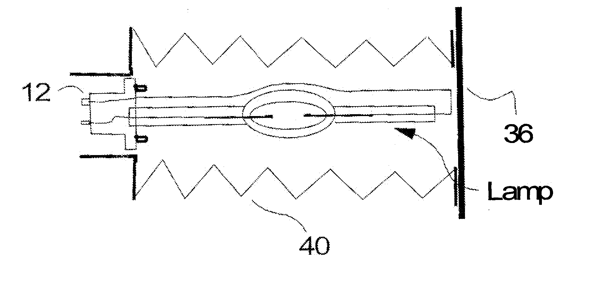
[0012] It is a third advantage of this invention to enable the utilization of lower cost, higher power shorter life, arc lamps in high usage applications, such as in consumer projection televisions thereby reducing the average cost of projector usage.
[0013] It is a fourth objection of this invention to combine the eele-enhanced® Lamp reflector module technology with an end-user replaceable arc lamp and with an installation / removal tool (protective enclosure) that increases operator safety. SUMMARY OF THE INVENTION
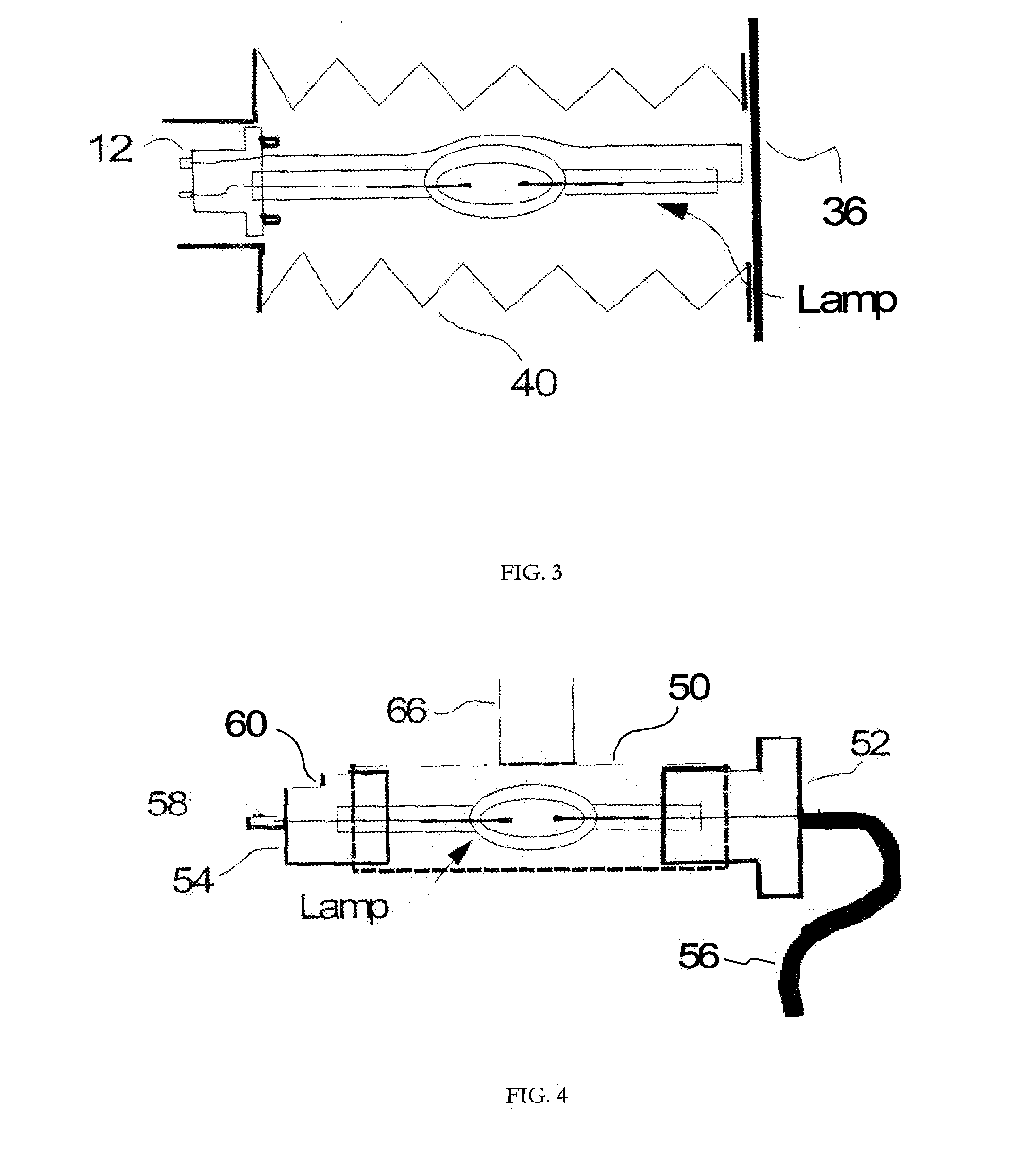
[0014] The present invention is directed to a delivery system that provides a “safer”, lamp replacement inside a lamp assembly and in particular, for use in combination with an elliptical, a parabolic and / or eele-enhanced® reflectors.
[0015] In a first embodiment of the present invention, the combination of a collapsible protective enclosure and the reflector system encloses at least the critical portion of the lamp installation, i.e. until the lamp with its respective mounting socket or sockets is fully seated in a respective lamp holder or when it respectively is being removed from its lamp holder. The preferred removal process according to this invention is performed when the lamp has cooled down to room temperature to minimize any pressure inside the lamp envelope leading to envelope fractures.

Problems solved by technology

However, such a lamp exchange, when implemented with prior art technology, can lead to potentially new problems.
The envelope of the lamp is typically sensitive to finger prints, which if incidentally left thereon, for example, during installation, can lead to, inter alia, an accelerated weakening of the envelope wall, wherein such acceleration is likely to precipitate a premature envelope fracture, whether during the normal operation of the lamp or even during its startup phase.
During normal operation of an arc lamp, the mechanical fragility of the envelope structure increases with age due to increased quartz devitrification.
Hence, this combined with the fact that most arc lamps have a much higher than atmospheric gas pressure during normal operation, and in particular the short arc Xe lamp types often have a higher than atmosphere fill pressure even when not operated, any handling of the lamp having such weakened envelope structure can yield a fracture of the envelope, and potentially personal injuries.
Therefore the handling of bare lamps, whether during their installation and / or, more importantly, during their removal, is critical, as such handling effects not only the maximum achievable lamp lifetime, but also potentially exposes the person removing the lamp to sharp glass pieces and / or Hg vapors, among other possible health risks.
However, for high volume, consumer type illumination products, like home entertainment micro display projection display systems, alignment of a replacement lamp by the consumer (an end user) in addition to the expense of training an end user in safe handling an unprotected lamp, has thus far been impractical based on current illumination technology.
This is an inefficient use of resources and adds a significant increase to the cost of ownership, i.e. at typically 15-40% of the cost of a new product.
However, in these as well as other patents, references are limited to special alignment features between a lamp that has been pre-aligned and cemented to a lamp socket incorporating respective alignment features; and a reflector having matching mechanical preparations thereby enabling alignment between the mounted lamp and the reflector housing resulting in reduced lamp position error.
However, there is an absence of any reference disclosed as to how the lamp exchange process may be made sufficiently “safe” for consumer end user installers.
However, it does not disclose how such an exchange can be performed sufficiently “safe” by an end-user, Thus, while '700 to Strobl enables a double-sided mounted Lamp-Reflector combination that is about 2×less sensitive to the lamp / reflector alignment (than elliptical or parabolic reflectors), and that, because of its double end mounting system is also much less sensitive to operator mounting errors, and therefore makes such an end user replaceable lamp option more practical, there still is a need to provide a lamp replacement method and / or system that makes an end-user replaceable lamp option sufficiently “safe” for the consumer projection and fiber optic illumination field.

Method used


Image

  • Delivery System for Removable Lamp
  • Delivery System for Removable Lamp
  • Delivery System for Removable Lamp

Examples


Embodiment Construction

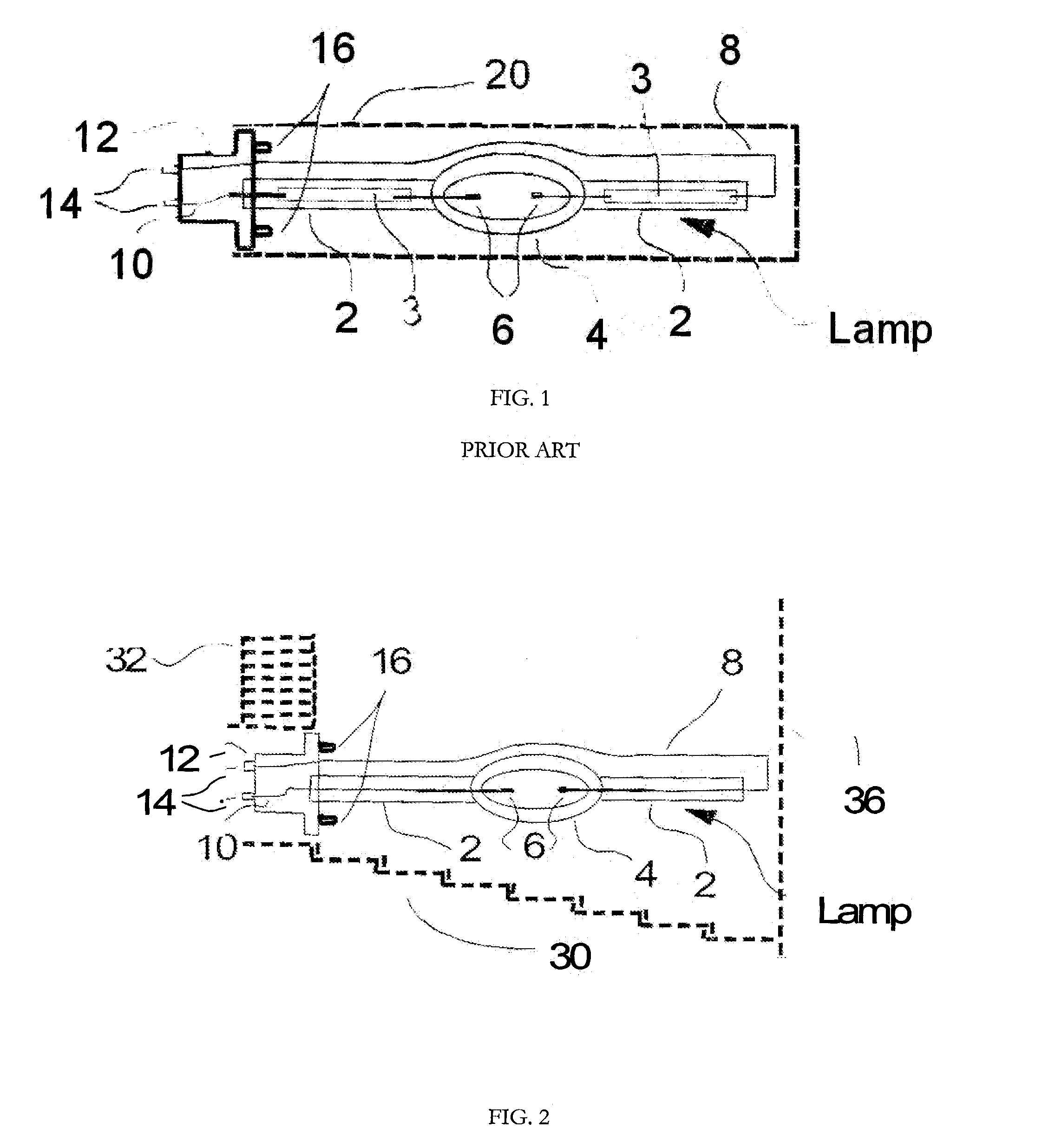
[0029] The present invention is directed to provide a delivery method and system that enables an end-user to replace a lamp inside a lamp reflector module in a safer way. In particular, this invention pertains to the field of micro display based projection display systems and fiber optic light sources. FIG. 1 illustrates a prior art delivery system for an automotive single end mounted arc lamp. The two lampposts 2, two Molybdenum foils 3, the envelope 4, and the two electrodes 6 together form the Lamp. The Lamp is electrically connected to the wires 8 and 10, and to a mounting socket 12, which has external electrical connections features 14 and alignment features 16 to help locate the electrode tips to the optimum alignment position with respect to a reflector with complimentary alignment features that match with the alignment features 16.

[0030] A transportation / shipping enclosure 20 encloses the Lamp and mechanically interlocks to the socket 12, for example, through a thread on th...


PUM


Abstract

The present invention is directed to a protective lamp delivery system that enables, inter alia, end-users to replace a lamp inside a lamp reflector module in a “safer” way, in particular, this invention pertains to the field of micro display based projection display systems and fiber optic light sources.

Description

RELATED APPLICATION(S) [0001] This application is related and claims priority to provisional applications (i) having Ser. No. 60 / 683,640 filed 23 May 2005, (ii) having Ser. No. 60 / 689,474 filed 10 Jun. 2005 and (iii) having Ser. No. 60 / 693,596 filed 25 Jun. 2005.BACKGROUND [0002] 1. Field of Invention [0003] The present invention is directed to the design and manufacturing of a protective lamp delivery system that enables, inter alia, end-users to perform a “safer” lamp replacement in the field of projection display systems and fiber optic illumination systems. [0004] 2. Description of Background [0005] A lamp assembly for a projection display system typically comprises a lamp housing, a reflector system, an electrical connection system, and a lamp. When only a lamp with a prealigned mounting socket is being replaced by an end user instead of the total lamp assembly, the cost of a lamp replacement can be, in principle, significantly reduced. However, such a lamp exchange, when imple...

Claims


Application Information

Patent Timeline
Patent Type & Authority Applications(United States)
IPC IPC(8): F21S8/06
CPCF21V17/007H01J61/86H01J9/003F21V19/04
Inventor STROBL, KARLHEINZSHEN, LI
Owner STROBL KARLHEINZ
Learn More