Boat propeller

a propeller and boat technology, applied in the direction of marine propulsion, liquid fuel engines, vessel construction, etc., can solve the problems of boat current horsepower ratings that far exceed the design capabilities of such a conventional bushing, rubber bushing slips and melts, and the bushing does not return to its normal size in seconds,

Active Publication Date: 2006-11-23
DEAN PETER
View PDF45 Cites 14 Cited by
  • Summary
  • Abstract
  • Description
  • Claims
  • Application Information

AI Technical Summary

Benefits of technology

[0009] The inner hub assembly of the propeller is spaced therefrom the central hub member by a plurality of resilient spacer members. The resilient spacer members are designed to absorb impact forces from the propeller, as well as harmonic vibration from the motor. The cushion provided by the resilient spacer members protects the drive shaft from damage due to the aforementioned impact forces and harmonic vibration.

Problems solved by technology

However, current horsepower ratings of boats far exceed the design capabilities of such a conventional bushing.
With so much torque under impact, the rubber bushing slips and melts.
As a result, the bushing does not return to its normal size and becomes unusable in seconds.
The damaged conventional bushing remains loose within the propeller bore, leaving the boat drive system useless and the boat undriveable.
While this method reduces failures akin to the ones mentioned above with the conventional rubber bushings, it does not provide any protection for the drive train under impact, it does not absorb any harmonic vibration from the motor or drive train, and it does not remain sufficiently tight on the propeller shaft.
The latter issue induces a rattle in the propeller shaft and produces operating noise.
It also promotes wear and tear on all the drive components.

Method used


Image

  • Boat propeller
  • Boat propeller
  • Boat propeller

Examples


Embodiment Construction

[0019] The present invention is more particularly described in the following exemplary embodiments that are intended as illustrative only since numerous modifications and variations therein will be apparent to those skilled in the art. As used herein, “a,”“an,” or “the” can mean one or more, depending upon the context in which it is used. The preferred embodiments are now described with reference to the figures, in which like reference characters indicate like parts throughout the several views.

[0020] Ranges may be expressed herein as from “about” one particular value, and / or to “about” another particular value. When such a range is expressed, another embodiment includes from the one particular value and / or to the other particular value. Similarly, when values are expressed as approximations, by use of the antecedent “about,” it will be understood that the particular value forms another embodiment.

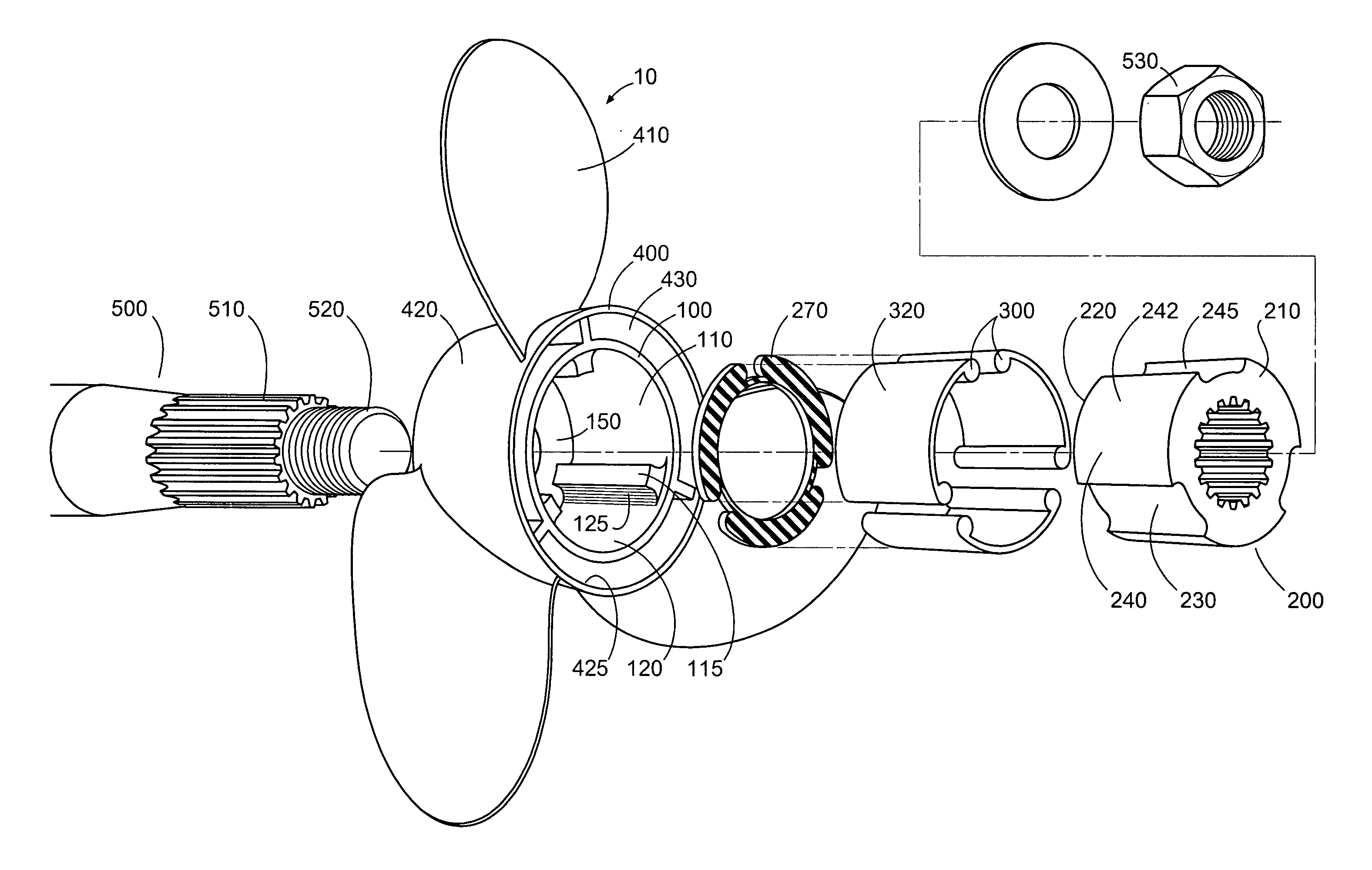
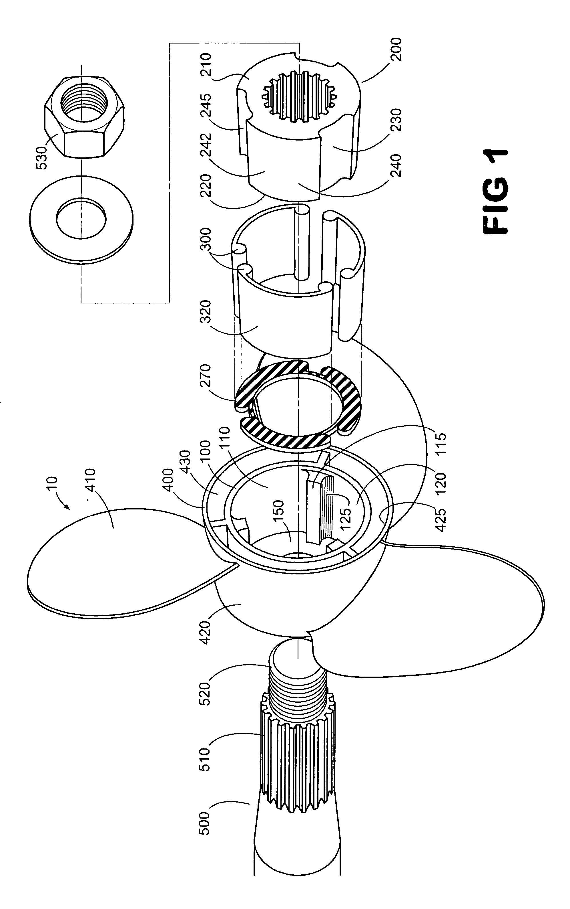
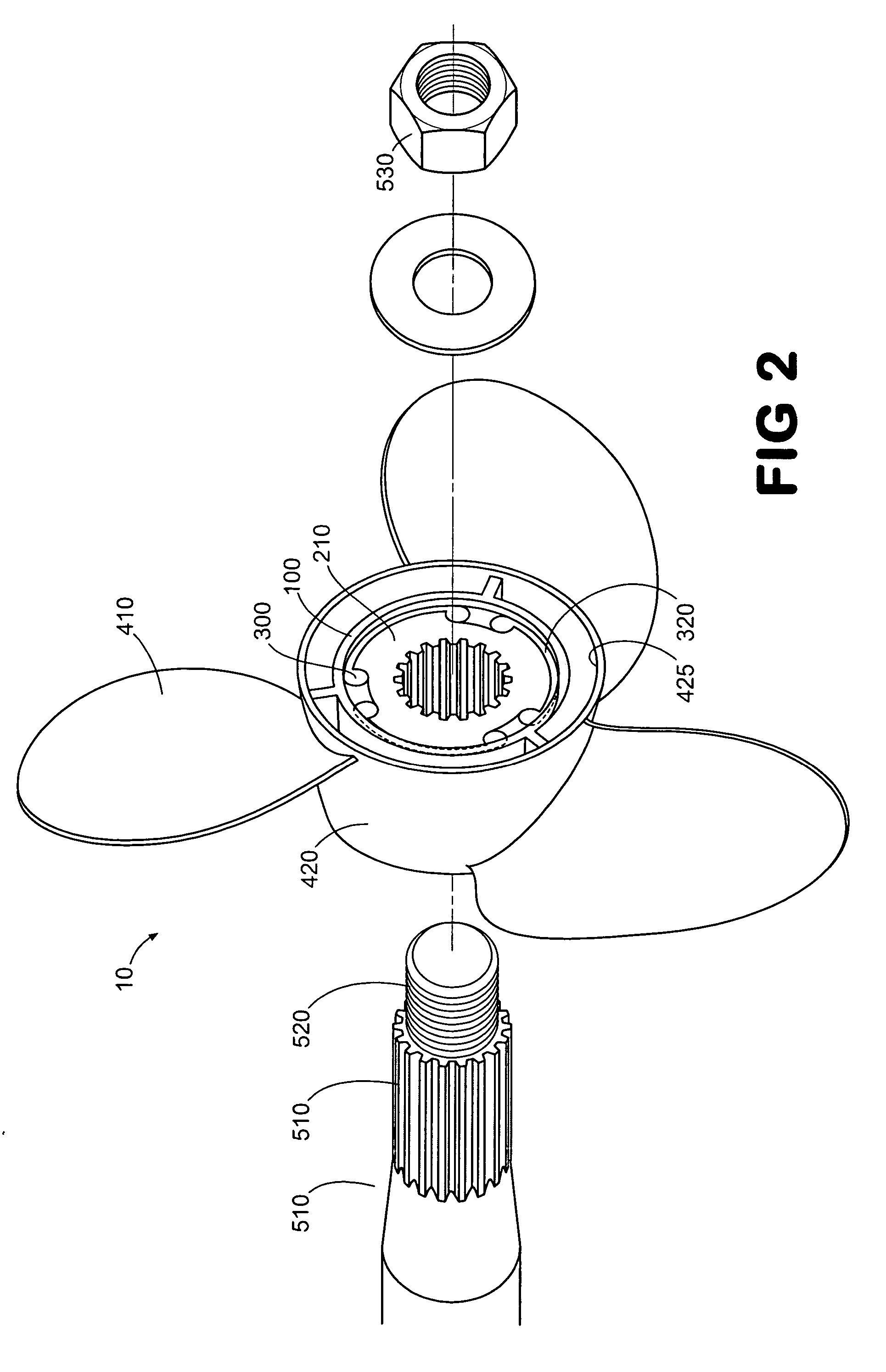
[0021] In one aspect of the present invention for a boat propeller 10 having a longi...


PUM


Abstract

A boat propeller comprising a central hub member and an inner hub assembly that defines a longitudinally extending bore having an inner surface. The exterior surface of the central hub member is sized and shaped for disposition therein the bore of the inner hub assembly in a complementary fashion. In one aspect, the propeller may also comprise a plurality of resilient spacer members positioned such that that the exterior surface of the central hub member is spaced from the inner surface of the bore.

Description

FIELD OF THE INVENTION [0001] The present invention relates to a propeller for a boat, more specifically to a propeller for a higher horsepower motor. BACKGROUND OF THE INVENTION [0002] The bushing system design for marine propellers has remained relatively unchanged since the early 1940's. Typically, a bushing is used to make a connection between the propeller body and the drive hub on the propeller shaft. The conventional bushing generally is formed from a hard rubber and makes the connection using friction. The rubber bushing is bonded to a center hub made of metal or plastic and the rubber is designed to be larger than the hole in which it is to be inserted. An installation funnel is used to compress the diameter of the rubber bushing to enable it to be inserted into the propeller bore. One of the benefits of this conventional design is that it gives both impact protection and harmonic vibration absorption protection. Another benefit of this conventional design is that, under im...

Claims


Application Information

Patent Timeline
Patent Type & Authority Applications(United States)
IPC IPC(8): F04D29/26
CPCB63H1/20
Inventor DEAN, PETER
Owner DEAN PETER
Why Eureka
Try Eureka