Method and system for finding tooth features on a virtual three-dimensional model

a three-dimensional model and virtual technology, applied in the field of computerized techniques for orthodontic treatment planning for human patients, can solve the problems of large volume of images and data involved, limited in their functionalities and scope, and substantial amount of manual work involved in these steps, and achieve the effect of minimizing the differences of z-coordinates

Inactive Publication Date: 2006-11-23
ORAMETRIX
View PDF8 Cites 73 Cited by
  • Summary
  • Abstract
  • Description
  • Claims
  • Application Information

AI Technical Summary

Benefits of technology

[0029] a) If there are at least three cusp tips, then the TAS is rotated in such a way that all cusp tips have (approximately) the same z-coordinate. If there are three cusp tips, they will

Problems solved by technology

Thus, there is a large volume of images and data involved in the diagnosis and treatment planning process.
There are some computerized tools available to aid the practitioner in these data conversion and reduction steps, for example to convert cephalometric x-rays (i.e., 2 dimensional x-ray photographs showing a lateral view of the head and jaws, including teeth) into points of interest with respect to soft tissue, hard tissue, etc., but they are limited in their functionalities and scope.
Even then, there is a fairly substantial amount of manual work involved in these steps.
Often, due to the complexities of the detailed steps and the time consuming nature of them, some practitioners take a shortcut, relying predominantly on their intuition to select a treatment plan.
All of these factors frequently contribute towards trial and error, hit-and-miss, lengthy and inefficient treatment plans that require numerous mid-course adjustments.
While at the beginning of treatment things generally run well as all teeth start to move at least into the right direction, at the e

Method used


Image

  • Method and system for finding tooth features on a virtual three-dimensional model
  • Method and system for finding tooth features on a virtual three-dimensional model
  • Method and system for finding tooth features on a virtual three-dimensional model

Examples


Embodiment Construction

[0076] Overview

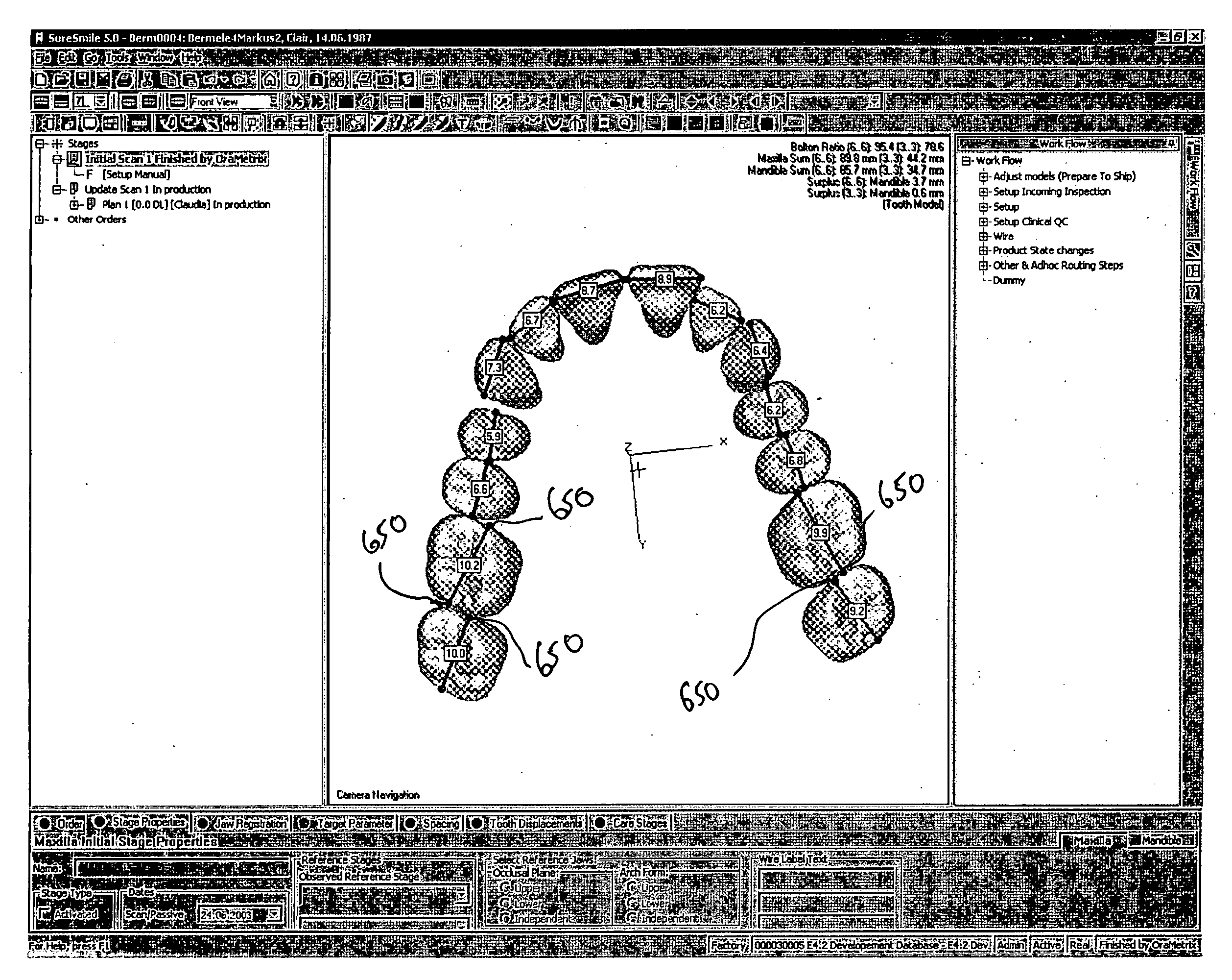
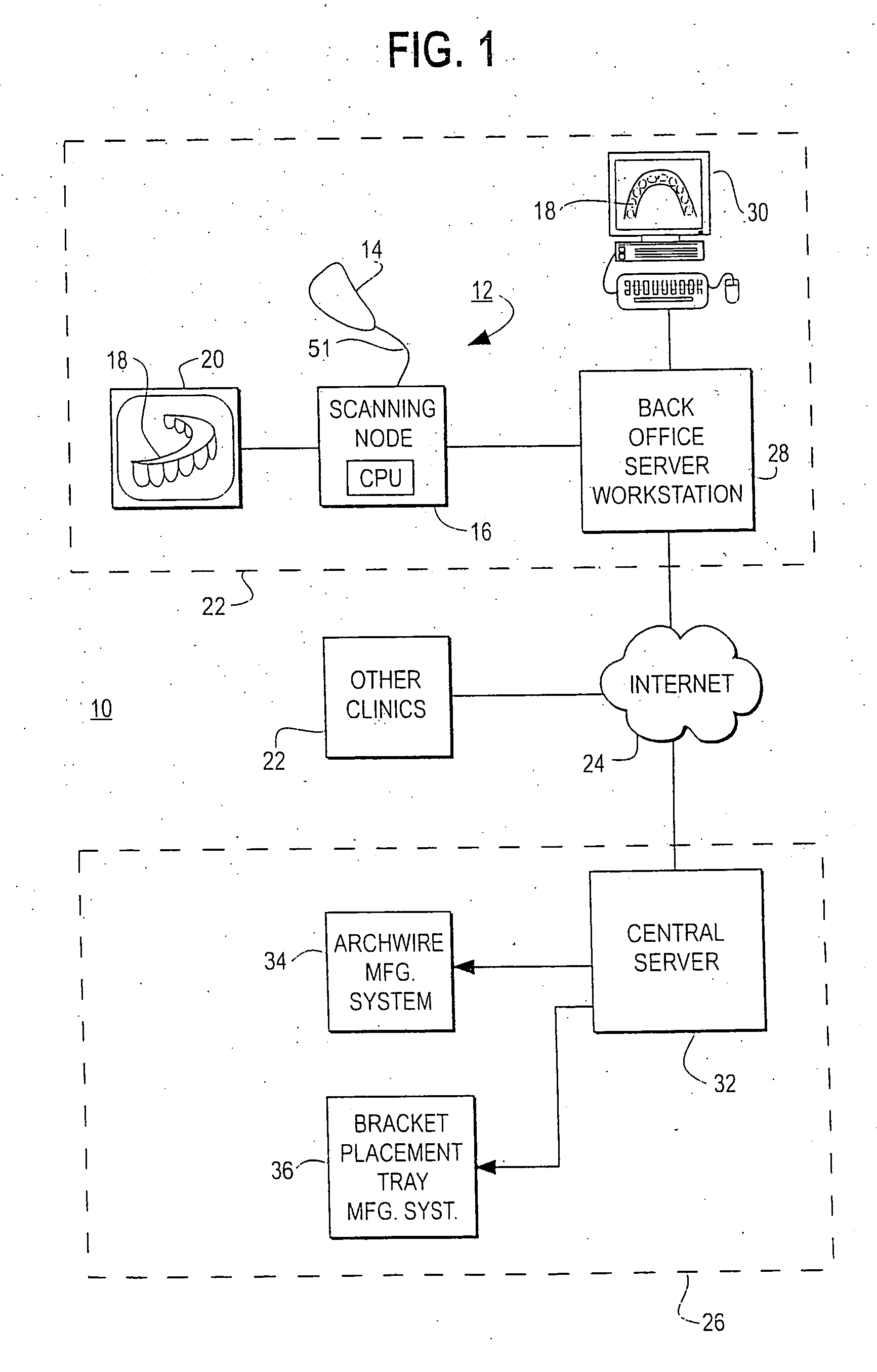
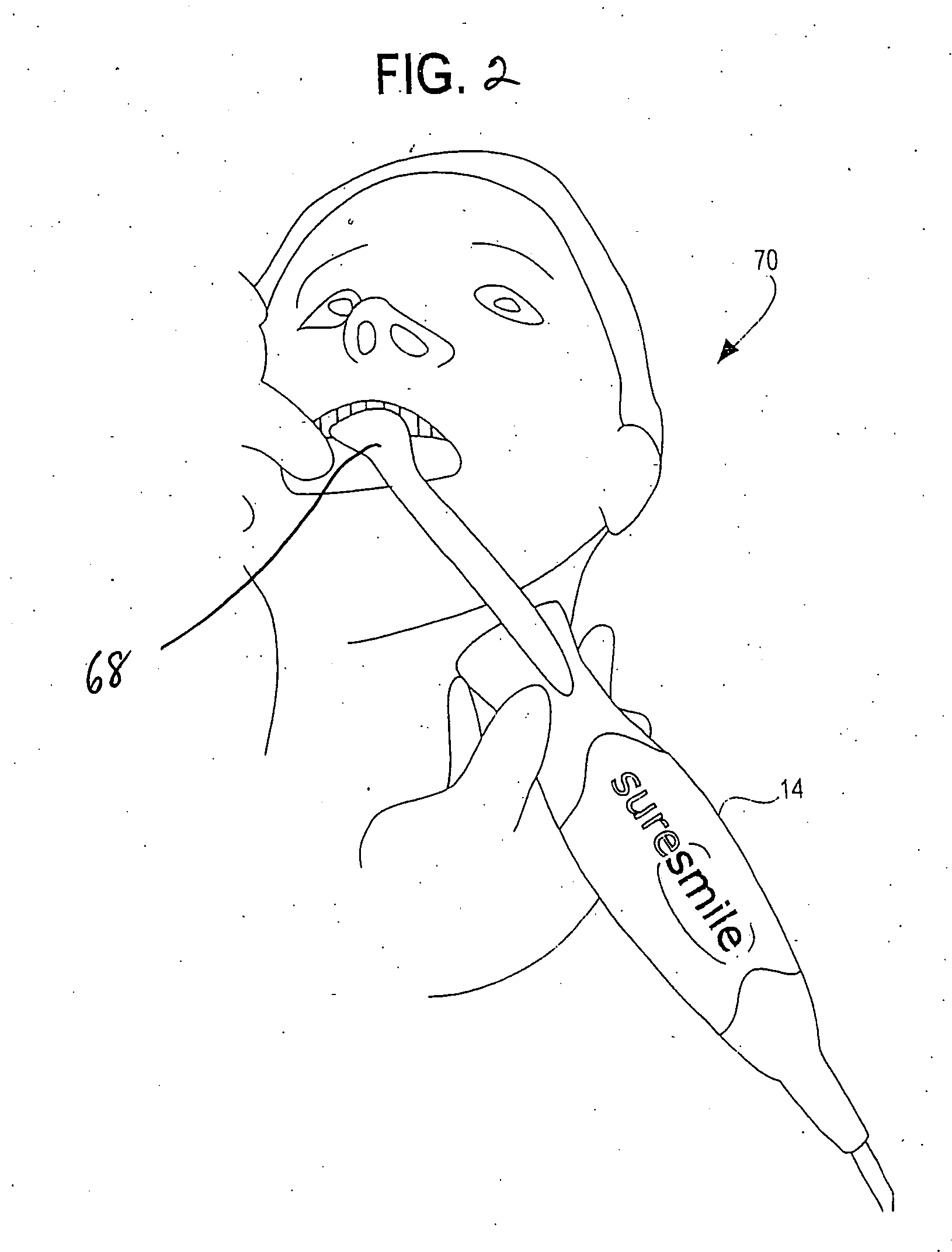
[0077]FIG. 1 is an illustration of an orthodontic care system 10 incorporating a scanner system 12. The scanner system 12 includes a hand-held scanner 14 that is used by the orthodontist or his assistant to acquire three-dimensional information of the dentition and associated anatomical structures of a patient. The images are processed in a scanning node or workstation 16 having a central processing unit, such as a general-purpose computer. The scanning node 16, either alone or in combination with a back-office server 28, generates a three-dimensional computer model 18 of the dentition and provides the orthodontist with a base of information for diagnosis, planning treatment, and monitoring care for the patient. The model 18 is displayed to the user on a monitor 20 connected to the scanning node 16.

[0078] As noted above, the scanner system 12 described in detail herein is optimized for in-vivo scanning of teeth, or alternatively, scanning a plaster model of the teet...


PUM


Abstract

A method and system are disclosed for finding virtual tooth features on virtual three-dimensional models of the teeth of patients. The tooth features comprise marginal ridges, cusp tips, contact points, central groove and buccal groove. Tooth axes system plays a key role in identifying the tooth features. An iterative method is disclosed for improving the accuracy of the tooth axes system. A virtual three-dimension model preferably obtained by scanning the dentition of a patient forms the basis for determining the tooth features. Tooth features are derived for all categories of teeth including molars, premolars, canines and front teeth. Tooth features are very helpful and used in planning orthodontic treatment. The tooth features are determined automatically using the computerized techniques; and can be manually adjusted when necessary.

Description

CROSS-REFERENCE TO RELATED APPLICATIONS [0001] This is a continuation-in-part of application entitled “METHOD AND SYSTEM FOR COMPREHENSIVE EVALUATION OF ORTHODONTIC CARE USING UNIFIED WORKSTATION,” Ser. No. 11 / 133,996, filed May 20, 2005, pending, the entire contents of which are incorporated by reference herein.BACKGROUND OF THE INVENTION [0002] A. Field of the Invention [0003] This invention relates to the field of computerized techniques for orthodontic treatment planning for human patients. More particularly, the invention is directed to finding virtual tooth features, which are very helpful and used in planning orthodontic treatment, on a virtual three-dimensional model of dentition. The tooth features are determined automatically using the computerized techniques; and can be manually adjusted when necessary. [0004] B. Description of Related Art [0005] The traditional process of diagnosis and treatment planning for a patient with orthodontic problems or disease typically consis...

Claims


Application Information

Patent Timeline
IPC IPC(8): A61C3/00A61C11/00
CPCA61C2007/004A61C7/00A61C13/0004A61C7/146A61C9/004A61C7/002A61C9/0046A61C9/0053G06F30/00G06T19/003
Inventor SPORBERT, PEERIMGRUND, HANSKAUFMANN, MARKUS
Owner ORAMETRIX
Why Eureka
Try Eureka