Reversed kinetic system for shoe sole

a kinetic system and shoe sole technology, applied in the direction of shoes, top-pieces, heels, etc., can solve the problems of inability to absorb energy and lack of damping effect, and achieve the effect of excellent contact with the ground and superb shock absorption

Inactive Publication Date: 2006-11-30
SOMMER ROLAND WILFRIED
View PDF28 Cites 12 Cited by
  • Summary
  • Abstract
  • Description
  • Claims
  • Application Information

AI Technical Summary

Benefits of technology

[0005] The present invention alleviates to a great extent the disadvantages of the known shoe soles by providing a shoe sole having a reversed kinetic system for absorbing shock energy generated during walking, running, jumping, etc. Shoes fitted with such a system provide superb shock absorption as well as excellent contact with the ground, similar to a foot in the sand.

Problems solved by technology

These chambers are simple compression springs that suffer from the disadvantage of having no damping effect.
In other words, compression springs have an elastic effect, but are incapable of absorbing energy.

Method used


Image

  • Reversed kinetic system for shoe sole
  • Reversed kinetic system for shoe sole
  • Reversed kinetic system for shoe sole

Examples


Embodiment Construction

[0033] In the following paragraphs, the present invention will be described in detail by way of example with reference to the attached drawings. Throughout this description, the preferred embodiment and examples shown should be considered as exemplars, rather than as limitations on the present invention. As used herein, the “present invention” refers to any one of the embodiments of the invention described herein, and any equivalents. Furthermore, reference to various feature(s) of the “present invention” throughout this document does not mean that all claimed embodiments or methods must include the referenced feature(s).

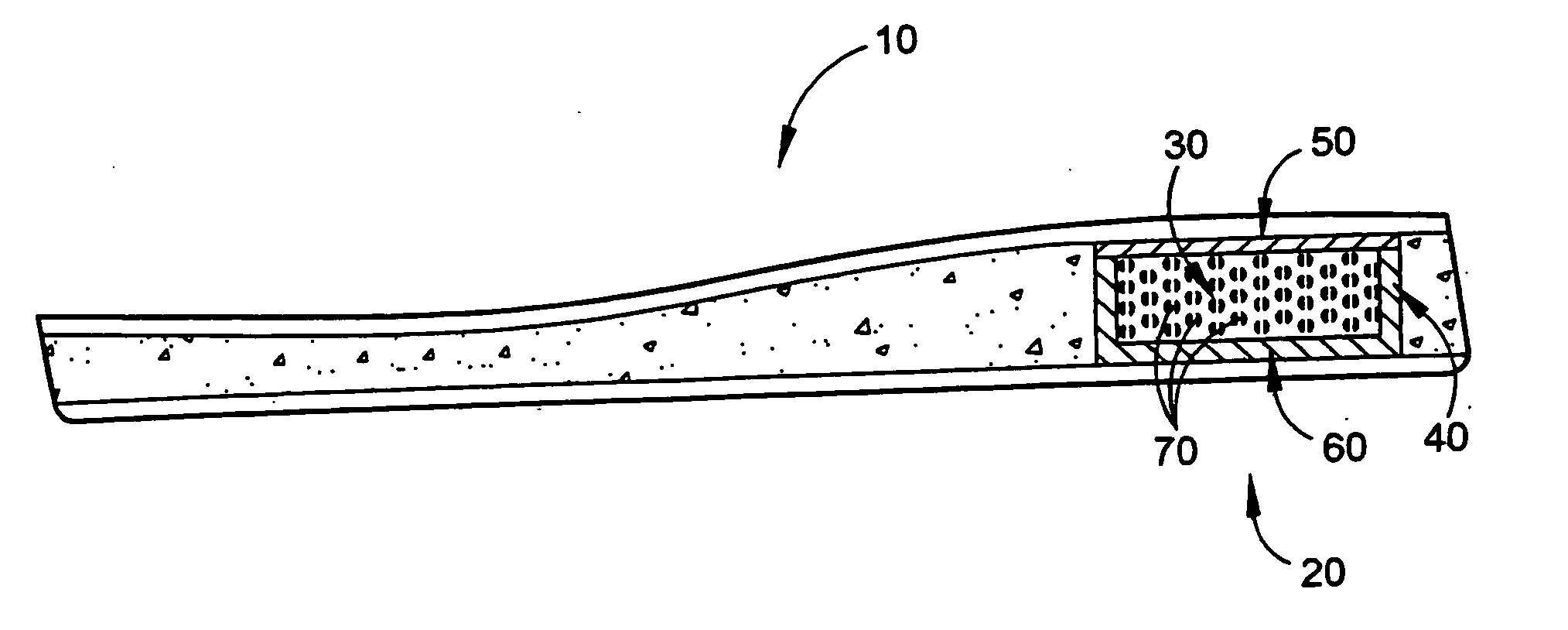
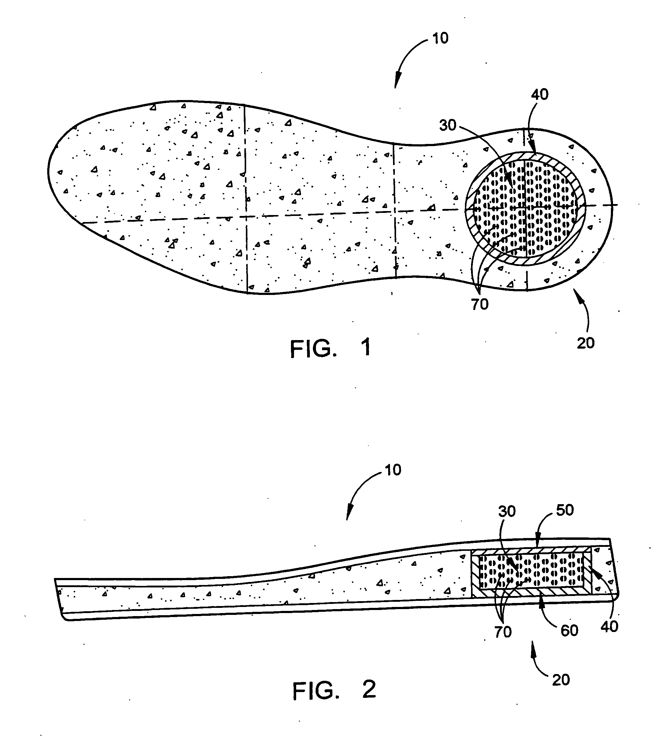
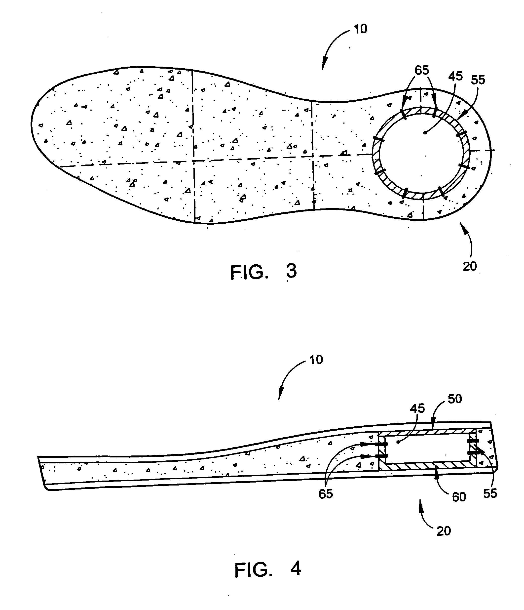
[0034]FIGS. 1-14 depict embodiments for a shoe sole having a reversed kinetic system, wherein energy absorption is achieve by the inelastic deformation of at least one energy absorber. In these embodiments, like elements have been numbered accordingly.

[0035] As seen in FIGS. 1 and 2, according to some embodiments, shoe sole 10 includes a reversed kinetic system 20...


PUM


Abstract

A reversed kinetic system for a shoe sole includes a fluid chamber containing fluid and a fluid expansion chamber in fluid communication with the fluid chamber, wherein the fluid chamber and fluid expansion chamber are separated by an elastic spring including at least one valve providing fluid communication. Each valve preferably comprises an inlet bore through the elastic spring and a yieldable diaphragm having a valve bore, whereby foot pressure on the fluid chamber causes fluid to dissipate through the valve bore into the fluid expansion chamber, wherein the dissipation of fluid through the valve bore causes friction and absorbs energy. Removing the foot pressure creates a negative pressure gradient in the fluid expansion chamber causing the yieldable diaphragm to release and allowing fluid to flow back into the fluid chamber through the inlet bore.

Description

RELATED APPLICATION [0001] This application is a continuation-in-part application claiming priority from co-pending U.S. application Ser. No. 10 / 367,297, filed on Feb. 14, 2006, the contents of which are hereby incorporated by reference as if set forth in its entirety.FIELD OF THE INVENTION [0002] The present invention is directed to a reversed kinetic system for a shoe sole. BACKGROUND [0003] Shoe soles having gas or gel chambers have been around for many years. These chambers are simple compression springs that suffer from the disadvantage of having no damping effect. Although compression springs are capable of delaying a force transfer, they still return any induced or loaded force without loss. In other words, compression springs have an elastic effect, but are incapable of absorbing energy. [0004] Accordingly, there exists a need for a shoe sole having a damping system capable of absorbing energy. SUMMARY OF THE INVENTION [0005] The present invention alleviates to a great exten...

Claims


Application Information

Patent Timeline
Patent Type & Authority Applications(United States)
IPC IPC(8): A43B13/18A43B13/20A43B21/26A43B21/28
CPCA43B13/189A43B21/285A43B21/265A43B13/203
Inventor SOMMER, ROLAND WILFRIED
Owner SOMMER ROLAND WILFRIED
Why Eureka
Try Eureka