Work machine having boundary tracking system

a technology of boundary tracking and work machine, which is applied in the direction of vehicle position/course/altitude control, process and machine control, instruments, etc., can solve the problems of reducing the accuracy of delineation between ore, affecting the accuracy of delineation, and affecting the delineation of high-grade ore and low-grade or

Active Publication Date: 2006-11-30
CATERPILLAR INC
View PDF29 Cites 62 Cited by
  • Summary
  • Abstract
  • Description
  • Claims
  • Application Information

AI Technical Summary

Benefits of technology

[0007] One aspect of the present disclosure is directed to a boundary tracking system. The boundary tracking system includes a plurality of signal transmitting devices located to represent at least one boundary of a work site. The boundary tracking system also includes a receiving device configured to receive signals transmitted from one or more of the plurality of transmitting devices and to generate an output based on the received signals. The boundary tracking system also includes a controller configured to determine a location of at least one of the plurality of transmitting devices based on the output from the receiving device.
[0008] Another aspect of the present disclosure is directed to a method of tracking a boundary. The method includes receiving one or more signals from at least one of a plurality of transmitting devices located to represent at least one boundary. The method also includes determining a location of the at least one of the plurality of transmitting devices based on the one or more signals. The method also includes controlling at least one function of a work machine based on the location of the at least one of the plurality of transmitting devices.

Problems solved by technology

However, blasting may cause non-uniform movement of the rock-mass and, consequently, the boundaries between the high-grade ore, low-grade-ore and waste may shift.
These shifted boundaries may reduce the accurate delineation between ore and waste regions within the resulting muck pile.
The ore diluted with waste material may be sent to a concentrator for further processing, which may reduce the efficiency of the ore extraction process.
Although the use of BMMs described in the '499 publication may reduce ore loss or dilution resulting from rock movement following a blast, manual detection of the BMMs may be labor intensive and inefficient as the operator manually moves across the rock-mass, detects the BMMs, and plots BMM movement prior to the excavation process.
Further inefficiencies may be created as the work machine operator reads and interprets the plots during the excavation process.
Human error may be further increased as the operator may not be provided with an indication of the relative position of the work machine or work tool in relation to the BMMs or plot data.

Method used


Image

  • Work machine having boundary tracking system
  • Work machine having boundary tracking system
  • Work machine having boundary tracking system

Examples


Embodiment Construction

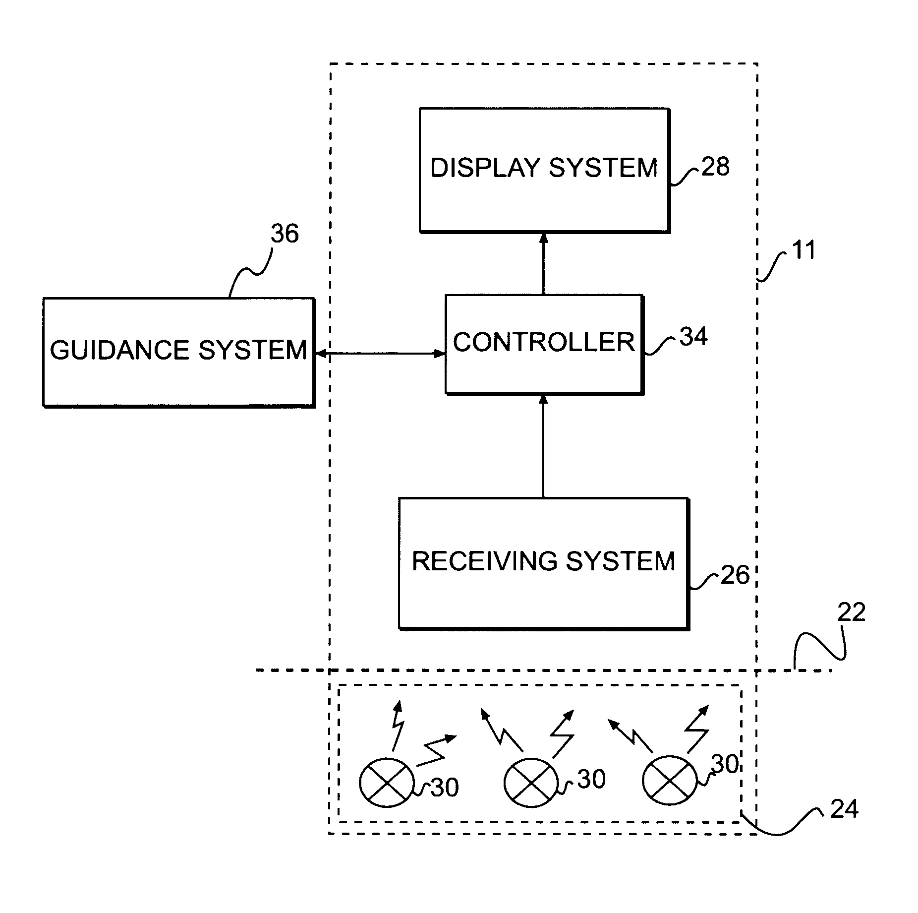
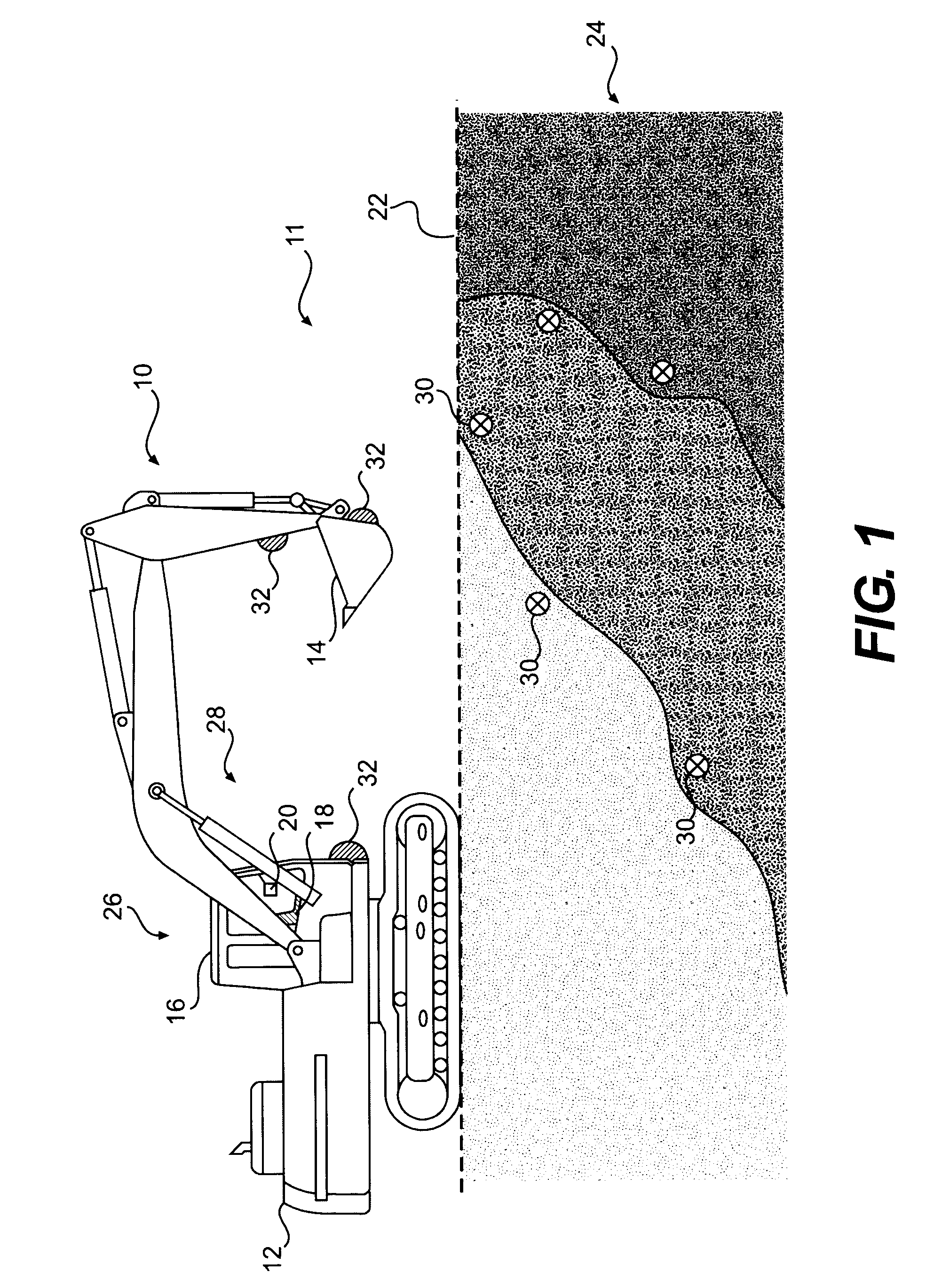
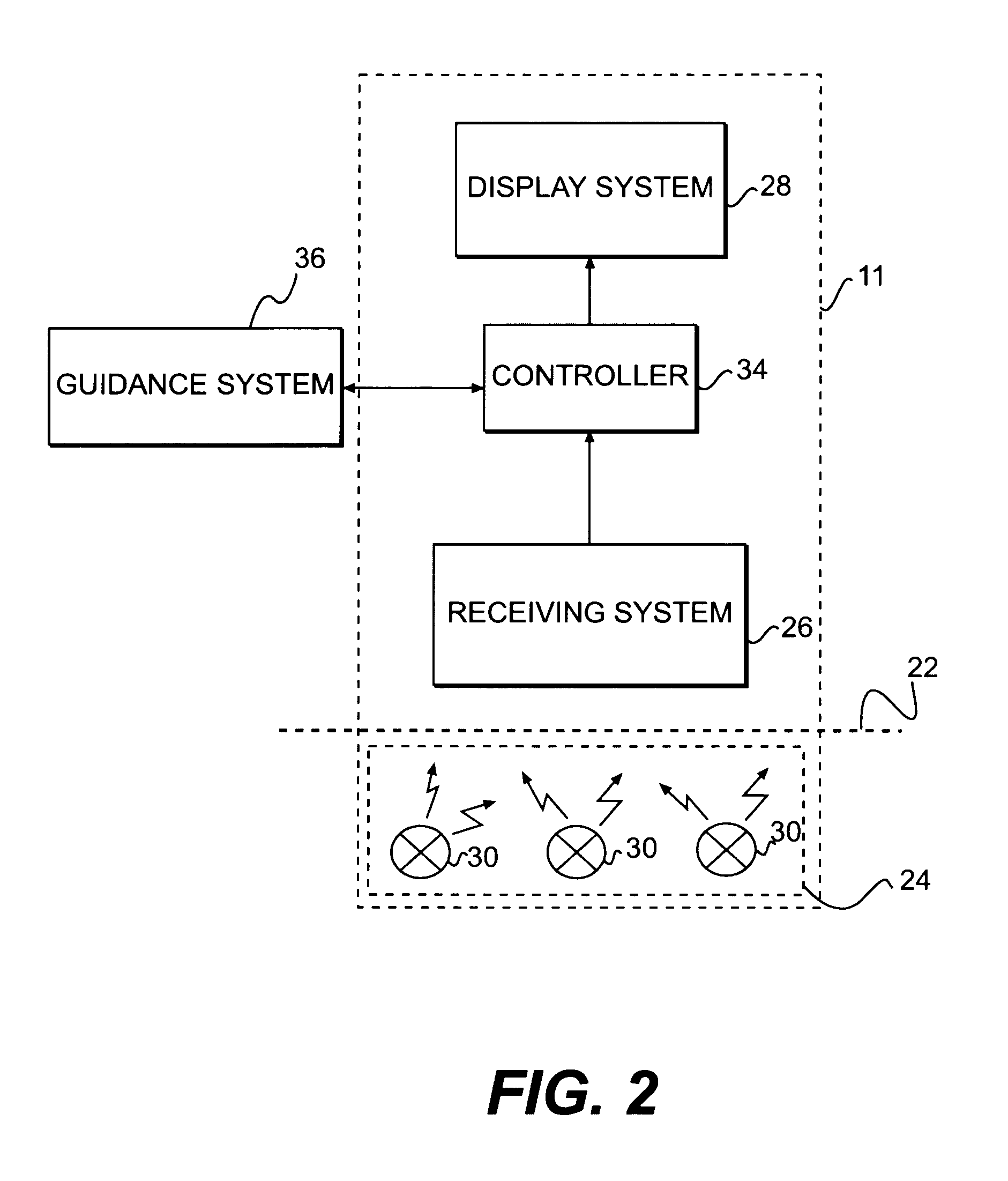
[0013]FIG. 1 illustrates an exemplary work machine 10 that may include components operational as part of a boundary tracking system 11. Work machine 10 may be a fixed or mobile machine that performs some type of operation associated with an industry such as mining, construction, farming, transportation, or any other industry known in the art. For example, work machine 10 may be an earth-moving machine such as an excavator, a shovel, a dozer, a loader, a backhoe, a motor grader, or any other earth moving machine. Work machine 10 may include a frame 12, at least one work tool 14, and an operator station 16.

[0014] Frame 12 may include any structural unit that supports movement of work machine 10 and / or work tool 14. Frame 12 may be, for example, a stationary base frame connecting a power source to a traction device, a movable frame member of a linkage system, or any other frame known in the art.

[0015] Work tool 14 may include any device used in the performance of a task. For example,...


PUM


Abstract

The boundary tracking system has a plurality of signal transmitting devices located to represent at least one boundary of a work site. The boundary tracking system also has a receiving device configured to receive signals transmitted from one or more of the plurality of transmitting devices and to generate an output based on the received signals. The boundary tracking system also has a controller configured to determine a location of at least one of the plurality of transmitting devices based on the output from the receiving device.

Description

TECHNICAL FIELD [0001] The present disclosure is directed to a work machine, and more particularly, to a work machine having a boundary tracking system. BACKGROUND [0002] Mining operations typically involve blasting and other techniques designed to fragment a rock-mass. Blasting may be necessary to fragment the rock-mass and loosen a resulting muck pile for efficient excavation. Prior to blasting, a geological survey of the rock-mass may be conducted to determine boundaries between high-grade ore, low-grade ore, and waste. However, blasting may cause non-uniform movement of the rock-mass and, consequently, the boundaries between the high-grade ore, low-grade-ore and waste may shift. [0003] These shifted boundaries may reduce the accurate delineation between ore and waste regions within the resulting muck pile. As a consequence, ore may cross a previously determined boundary and move into a region designated as waste, where it may be subsequently discarded. Also, dilution of the mine...

Claims


Application Information

Patent Timeline
Patent Type & Authority Applications(United States)
IPC IPC(8): E21C37/00E21C41/00E21C45/00E21C47/02G05D1/02G05D1/04E02F5/02
CPCE02F9/2025E21C35/08E02F9/26E02F9/245
Inventor GUDAT, ADAM JOHN
Owner CATERPILLAR INC
Why Eureka
Try Eureka