Apparatus and method for transferring samples from a source to a target

a technology of apparatus and target, applied in the field of analytical separation and combining samples, can solve the problems of expensive and time-consuming procedures, inconvenient cleaning of whole apparatus or devices, and ineffectiveness

Inactive Publication Date: 2006-11-30
FESTO CORPORATION
View PDF13 Cites 28 Cited by
  • Summary
  • Abstract
  • Description
  • Claims
  • Application Information

AI Technical Summary

Benefits of technology

[0028] Of course, the system can also be operated by selecting any pin combination within the array permitting quantitative collection of particles from a given magnetic suspension. This feature of quantitative separation and transfer allows for dividing a sample into sub-samples. Also, the present invention allows for the sample particles to be washed efficiently with a “flip-flop” movement of particles due to magnets moving under the sample wells.

Problems solved by technology

One drawback of the “first generation” separators relates to the fact that the stationary permanent magnets positioned below the micro-plates do not come into direct contact with the magnetic particles due to the thickness of the plate and vessel sides.
As a result, the magnetic field applied to the individual micro-plate wells is relatively weak due to the distance between the magnetic plate and the magnetic particles and separation is, therefore, somewhat inefficient.
The drawbacks of the above “second generation separators” reside in the fact that the magnetic rods or pins come into direct contact with the magnetic particles, so that if rinsing and sterilization is required, the whole apparatus or device has to be washed.
Such a procedure is expensive and time consuming.
Furthermore, even where the magnetic rods are covered with disposable protective tips, the collection of particles is not efficient since some of the particles remain in the suspension due to surface tension forces.
Another drawback of these devices reside in the fact that where a multi-pin device is used to collect magnetic particles from a plurality of wells, all of the pins are fixed to a movable head and travel up and down as a unit such that all of the samples from all the wells have to be collected at once in an “all or none” fashion.
Thus, it is not possible to selectively collect particles from only selected wells in an array.

Method used


Image

  • Apparatus and method for transferring samples from a source to a target
  • Apparatus and method for transferring samples from a source to a target
  • Apparatus and method for transferring samples from a source to a target

Examples


Embodiment Construction

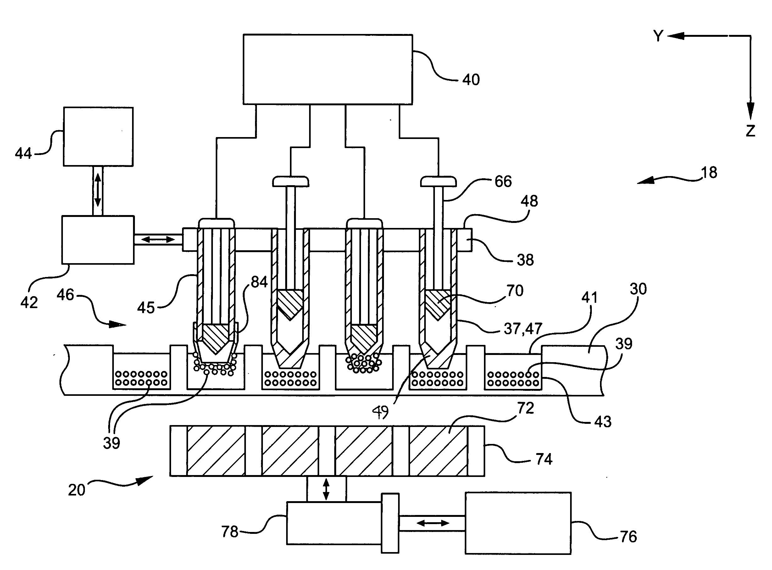
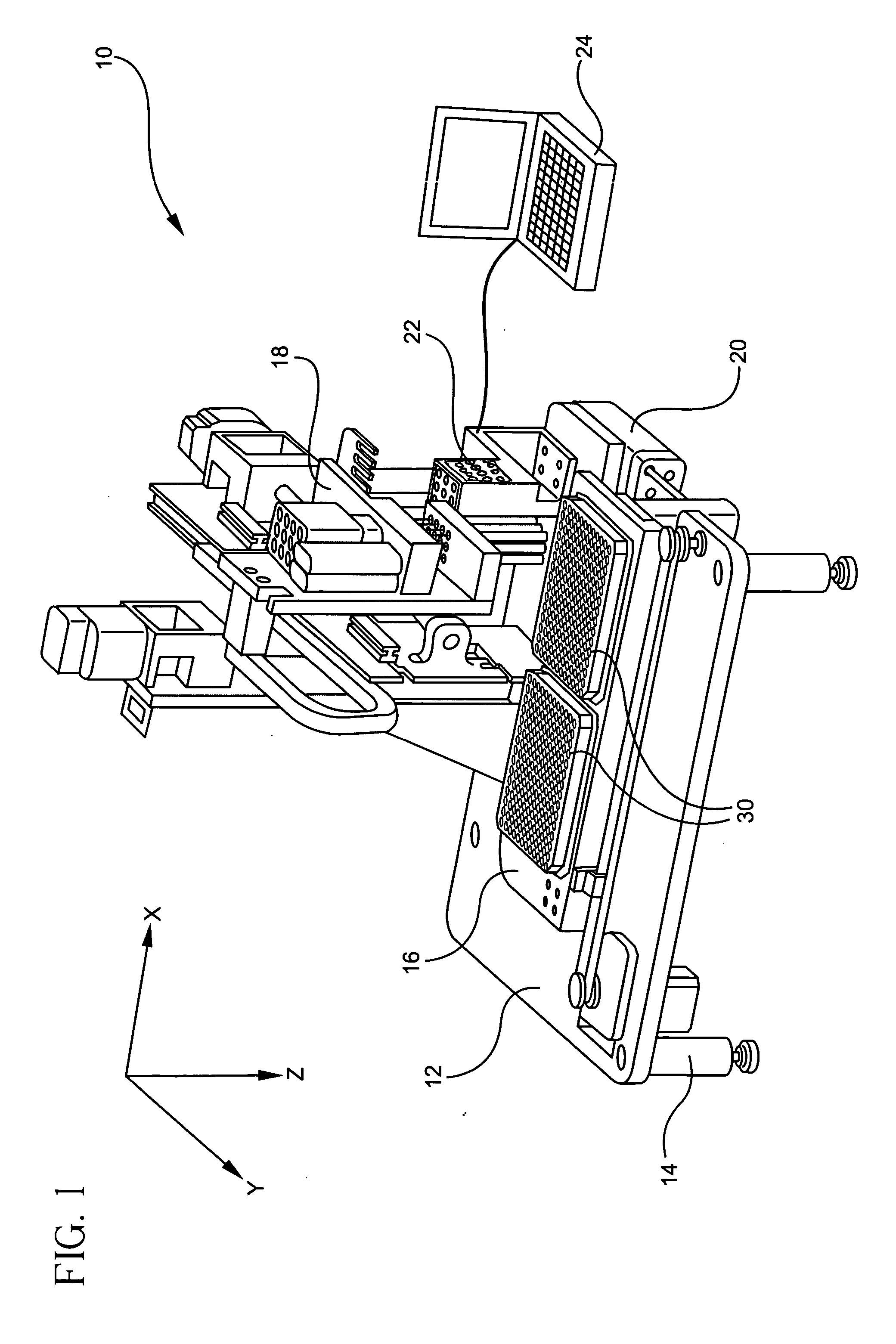
[0063] Referring first to FIG. 1, the pin control system 10 of the present invention generally includes five major functional components provided on a supporting structure or frame 12 having a plurality of legs 14 for supporting the system 10 on a surface. The major functional components of the system 10 include a vessel unit 16, a primary transfer unit 18, a secondary magnet unit 20, a tip insertion / removal station 22 and a central control unit 24.

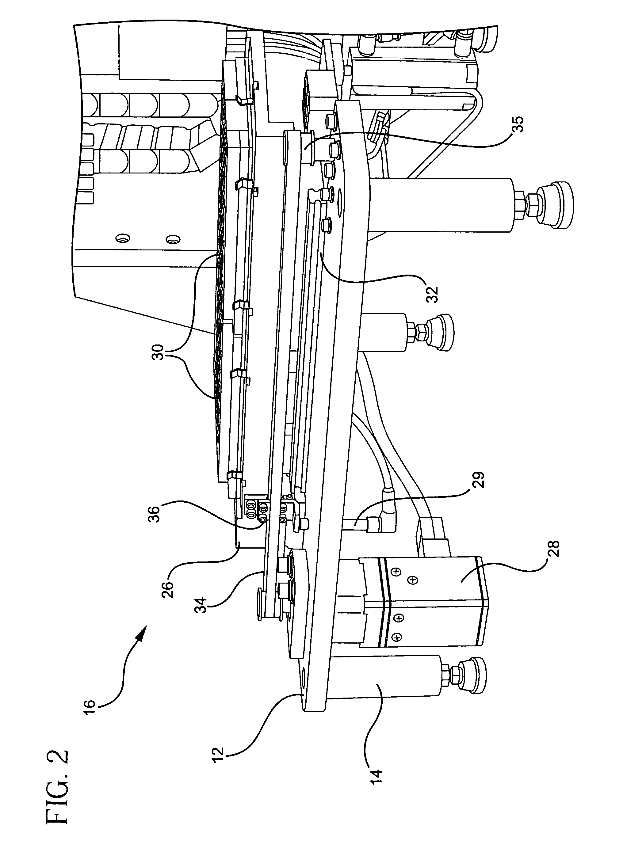
[0064] Referring additionally to FIG. 2, the vessel unit 16 preferably includes a translatable support plate 26 and a motor 28 for reciprocally translating the support plate in the x-direction with respect to the system frame 12, as shown in FIG. 1. The translatable support plate 26 supports a source vessel containing a sample to be transferred and a target vessel to which the sample is transported. It is of course conceivable for the support plate 26 to support multiple samples which can be simultaneously transported from respective sou...


PUM

PropertyMeasurementUnit
thicknessaaaaaaaaaa
voltageaaaaaaaaaa
movementaaaaaaaaaa

Abstract

A transfer unit for transferring a sample from a source vessel to a target vessel. The transfer unit includes a transfer device having a pin tip with a central bore terminating at a bottom wall, an actuating element movably disposed in the pin tip bore, an actuator rod for moving the actuating element and a compensating device connected between the actuating element and the actuator rod. The actuator rod moves the actuating element between a first position adjacent the tip bottom wall and a second position away from the bottom wall. Movement of the actuating element causes a sample in proximity to the pin tip to be alternately collected and released from the pin tip. Such movement also defines a stroke length for the actuator rod, wherein the compensating device compensates for any variations in the actuator rod stroke length. The transfer unit further includes a tip ejector for removing the disposable tips from the transfer device and a tip loading station for applying the tips to the transfer device.

Description

CROSS-REFERENCE TO RELATED U.S. APPLICATIONS [0001] This application is a continuation-in-part of U.S. application Ser. No. 11 / 135,962, filed on May 25, 2005.FIELD OF THE INVENTION [0002] The present invention relates generally to the field of analytical separation and combining of samples and, more particularly, to a system and apparatus for individually actuating and controlling a multiple array of collection members for transferring samples from a plurality of source vessels to a plurality of target vessels. BACKGROUND OF THE INVENTION [0003] Analytic and diagnostic procedures in the laboratory often require the transfer of a plurality of samples, simultaneously, from one array of liquid-containing wells to another. In order to transfer, add, collect or combine liquids, various multi-transferring systems have been devised. The most commonly used is a multi-pipette which collects liquid from an array of source wells for transfer to an array of target wells, simultaneously, by appl...

Claims


Application Information

Patent Timeline
Patent Type & Authority Applications(United States)
IPC IPC(8): G01N1/26G01N1/16
CPCB03C1/286G01N35/10G01N35/04B03C1/288B03C1/284
Inventor ZOBEL, HANS-JORGLEEMAN, GERARD WILLIAMPORAT, AMIRGOMBINSKY, MOSHE
Owner FESTO CORPORATION
Why Eureka
Try Eureka