Method of controlling an internal combustion engine

Active Publication Date: 2006-11-30
ROLLS ROYCE SOLUTIONS GMBH
View PDF3 Cites 23 Cited by
  • Summary
  • Abstract
  • Description
  • Claims
  • Application Information

AI Technical Summary

Benefits of technology

[0009] With the present invention, the properties of the individual injectors can be determined over their life. Since the properties of the individual fuel injectors are known, the injectors can be uniformly adjusted so that their injection behaviors are the same. The better knowledge of the injectors permits on optimiza

Problems solved by technology

In practice, however, there is the problem that, in an internal combustion engine with a common rail system, there is always some time delay between the start of the energization of the injectors, that is the injector needle actuation and the actu

Method used


Image

  • Method of controlling an internal combustion engine
  • Method of controlling an internal combustion engine
  • Method of controlling an internal combustion engine

Examples


Embodiment Construction

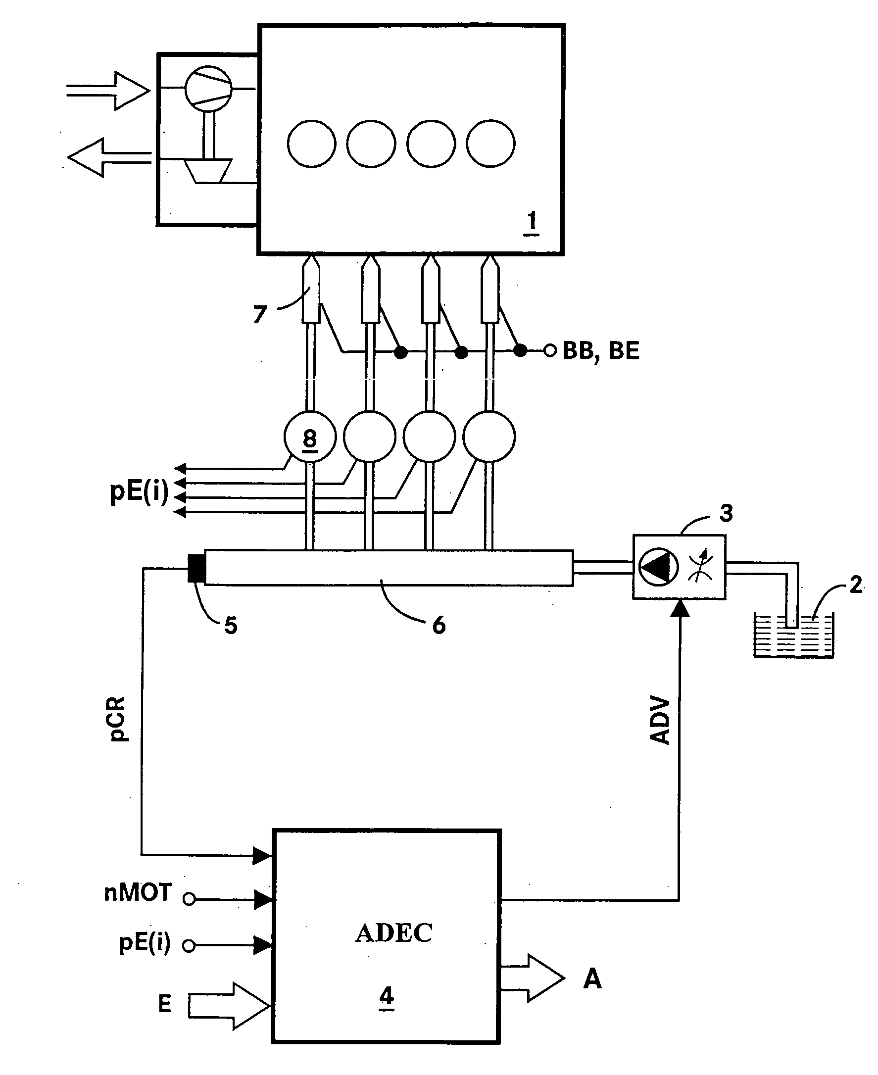
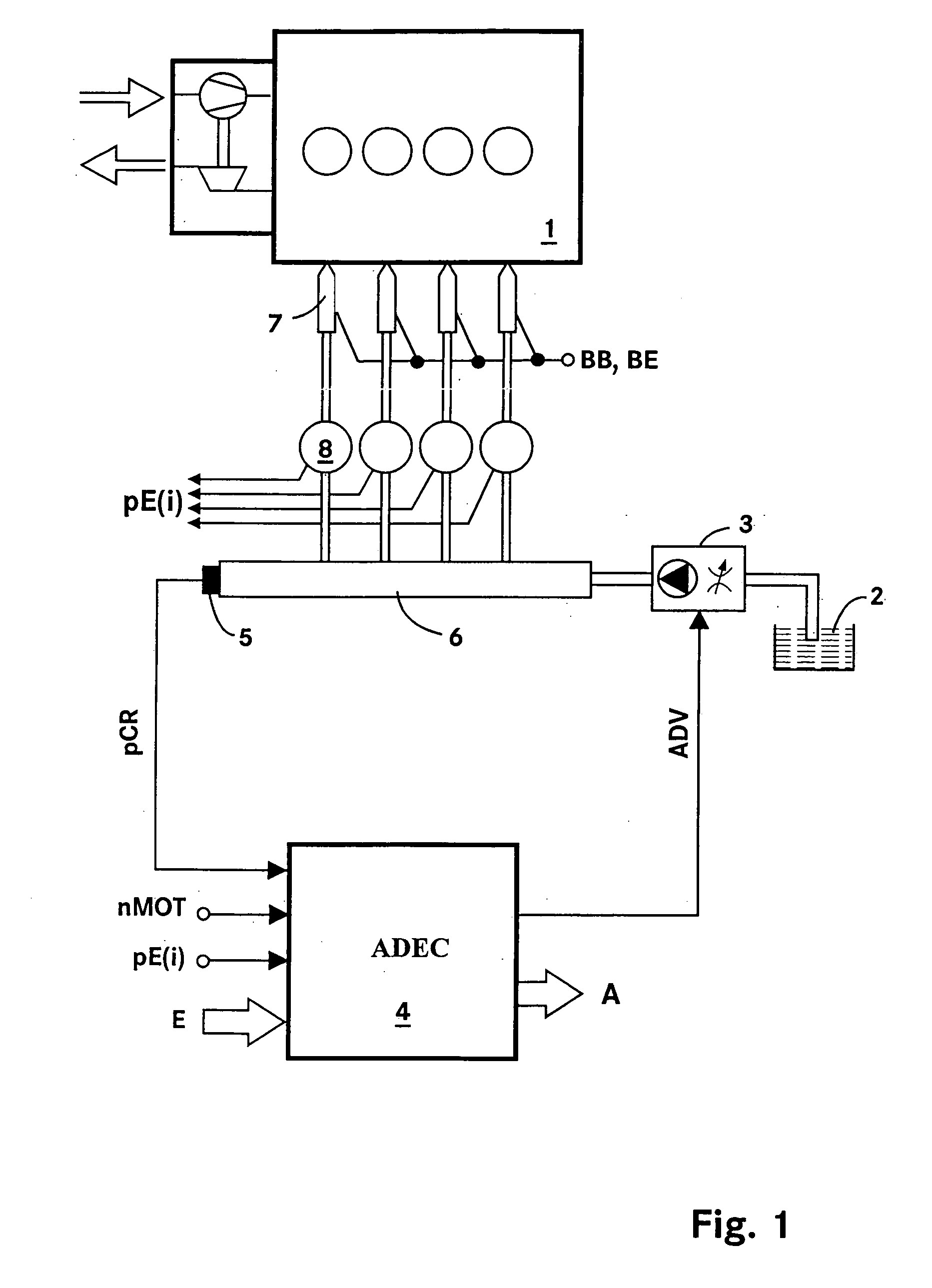
[0015]FIG. 1 shows schematically an electronically controlled internal combustion engine. In the internal combustion engine 1 shown the fuel is injected by way of a common rail system which comprises the following components: Pumps 3 with a suction throttle for pumping the fuel from a fuel tank 2, a rail 6, individual storage chambers 8, and injectors 7 for injecting the fuel into the combustion chambers of the internal combustion engine 1. In this system, the hydraulic resistance of the individual chambers 8 and the supply lines is appropriately adapted. For the invention, it is unimportant whether the rail 6 has a storage volume or is only a simple fuel supply line.

[0016] The operation of the internal combustion engine 1 is controlled by an electronic control unit (ADEC) 4. The electronic control unit 4 comprises the usual components of a microcomputer system, such as a microprocessor, I / O components, buffers and storage components (EEPROM, RAM). In the storage components, the op...


PUM


Abstract

In a method of controlling an internal combustion engine having a common rail fuel injection system including individual fuel storage chambers, wherein the pressure pattern of the fuel supplied to each injector can be determined and actual and virtual fuel injection ends and fuel injection begins are determined, the deviations from the desired fuel injection ends and from the fuel injection begins are calculated and the injectors are evaluated on the basis of the deviations and further control of the internal combustion engine is based on an evaluation of the fuel injectors.

Description

[0001] This is a Continuation-In-Part Application of International Application PCT / EP2005 / 001226 filed Feb. 8, 2006 and claiming the priority of German application 10 2004 006896.8 filed Feb. 12, 2004.BACKGROUND OF THE INVENTION [0002] The invention resides in a method of controlling an internal combustion engine including a common rail fuel injection system with individual storage chambers, wherein an actual injection end is determined from the pressure pattern of the individual storage chambers and a virtual injection begin is determined. [0003] In an internal combustion engine, the start and the end of the fuel injection determine to a large extend the quality of the combustion and the composition of the exhaust gas. In order to maintain legal limits, these two characteristic values are generally controlled by an electronic control unit. In practice, however, there is the problem that, in an internal combustion engine with a common rail system, there is always some time delay bet...

Claims


Application Information

Patent Timeline
IPC IPC(8): F02M65/00F02M57/02G01M15/00F02D41/00F02D41/22F02D41/38F02M63/00
CPCF02D41/008F02D41/221F02D2041/224F02D41/402F02D2041/2055F02D41/3809
Inventor KLOOS, ALBERTWILLMANN, MICHAELSCHMIDT, GUNTHERSPEETZEN, RALFMULLER, STEFANKUNZ, ANDREAS
Owner ROLLS ROYCE SOLUTIONS GMBH
Why Eureka
Try Eureka