
Sunshade with Illuminating Device

a technology of illuminating device and sunshade, which is applied in the direction of clothing, building types, construction, etc., can solve the problems of poor illumination space, big troubles, and difficult placement of main illuminating member in the central position of direct illuminating area, and achieve high light intensity

Inactive Publication Date: 2006-11-30
WU WEIDAN
View PDF10 Cites 17 Cited by
  • Summary
  • Abstract
  • Description
  • Claims
  • Application Information

AI Technical Summary

Benefits of technology

[0009] The object of the present invention is to provide a sunshade with a biased-arranging post, which has a centrally positioned main lighting apparatus providing a relatively high level of light intensity, thus a post portion of sunshade would not become an obstacle of illumination and for fixing a light member which gives a main luminary for the use of reading, playing games, operating a computer or leisure activities. The battery pack and associated solar panel are sufficient to allow the system to operate continuously for a time interval of several hours underneath the canopy without the need of an external power source.
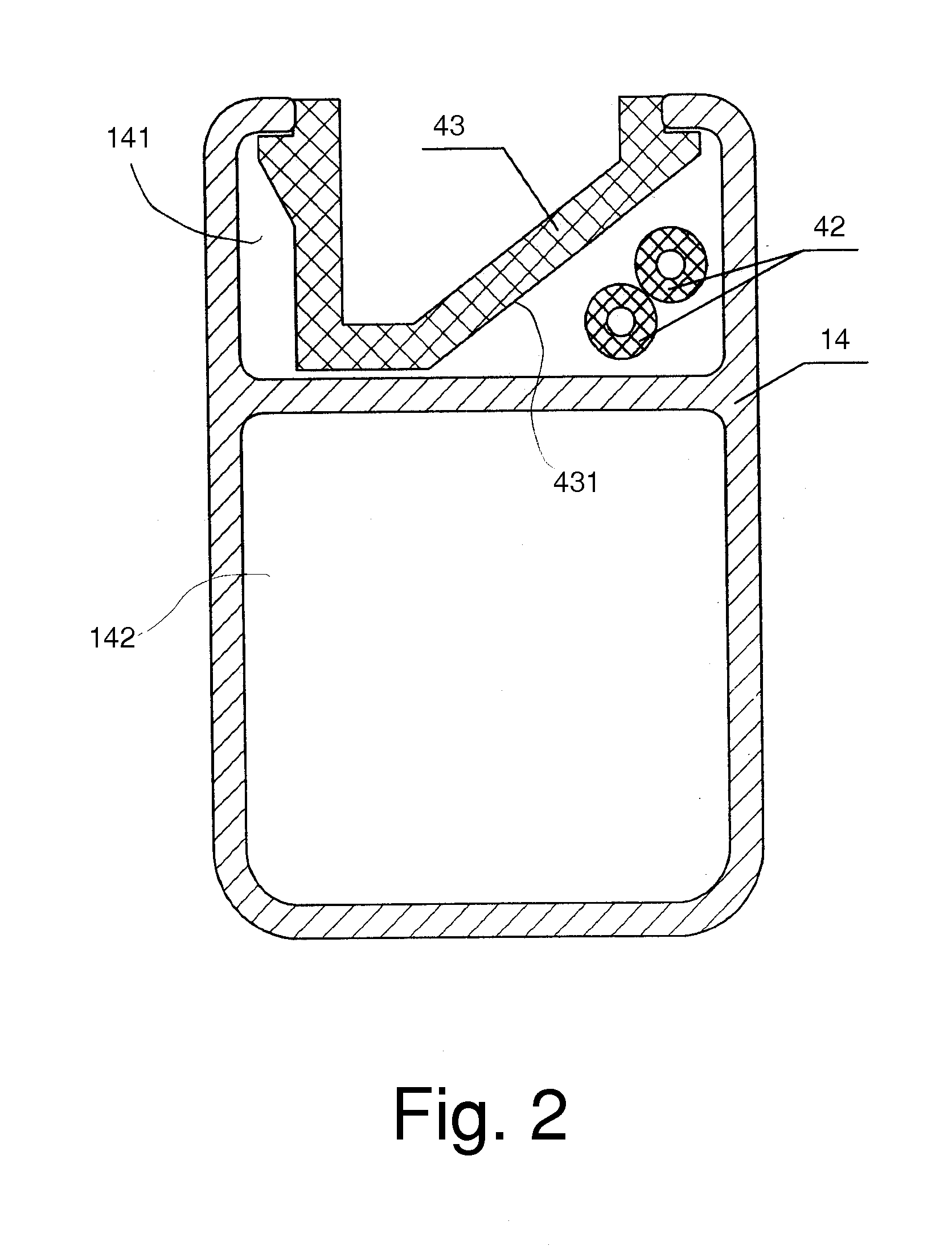
[0010] Another object of the present invention is to provide a reasonable construction of ribs, which provides an easy layout for wiring of many bulbs attached on the ribs.

Problems solved by technology

However, to use generator or long-extended wiring for supplying electricity in outdoor, some times brings big troubles.
Currently used conventional sunshade with illumination has a defect that due to a canopy post erects on the ground in the central position of sunshade, thus, the space for leisure activities and illumination is badly reduced.
It is hard to place a main illuminating member in the central position of the direct illuminating area.

Method used


Image

  • Sunshade with Illuminating Device
  • Sunshade with Illuminating Device
  • Sunshade with Illuminating Device

Examples


Embodiment Construction

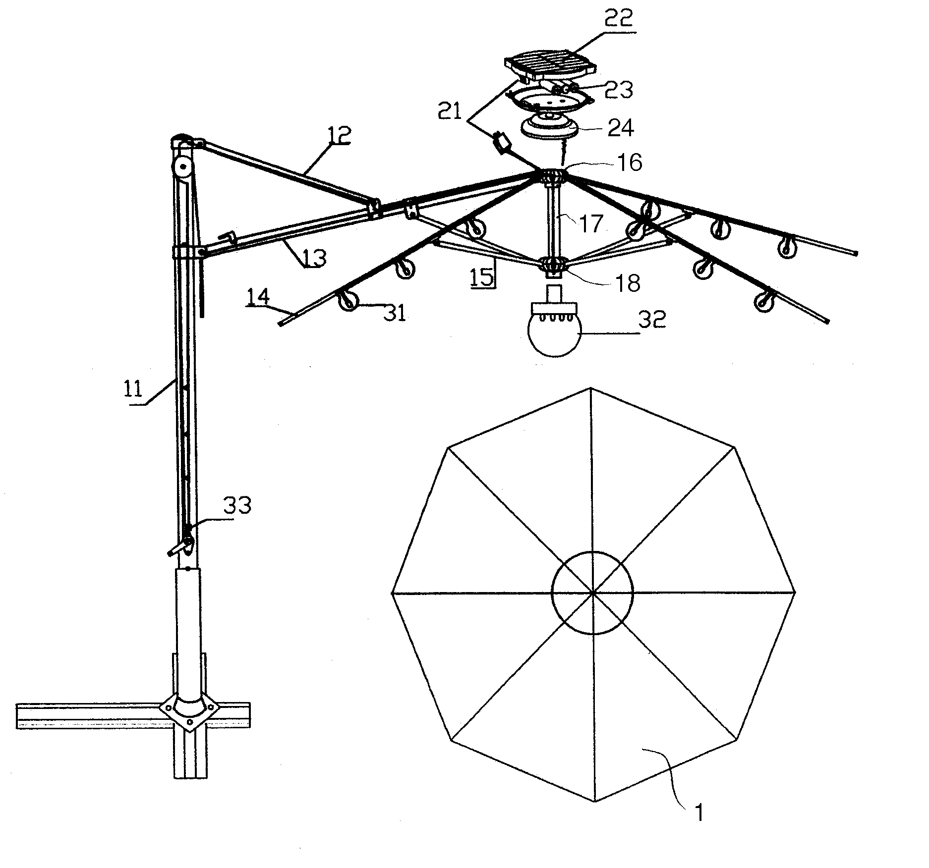
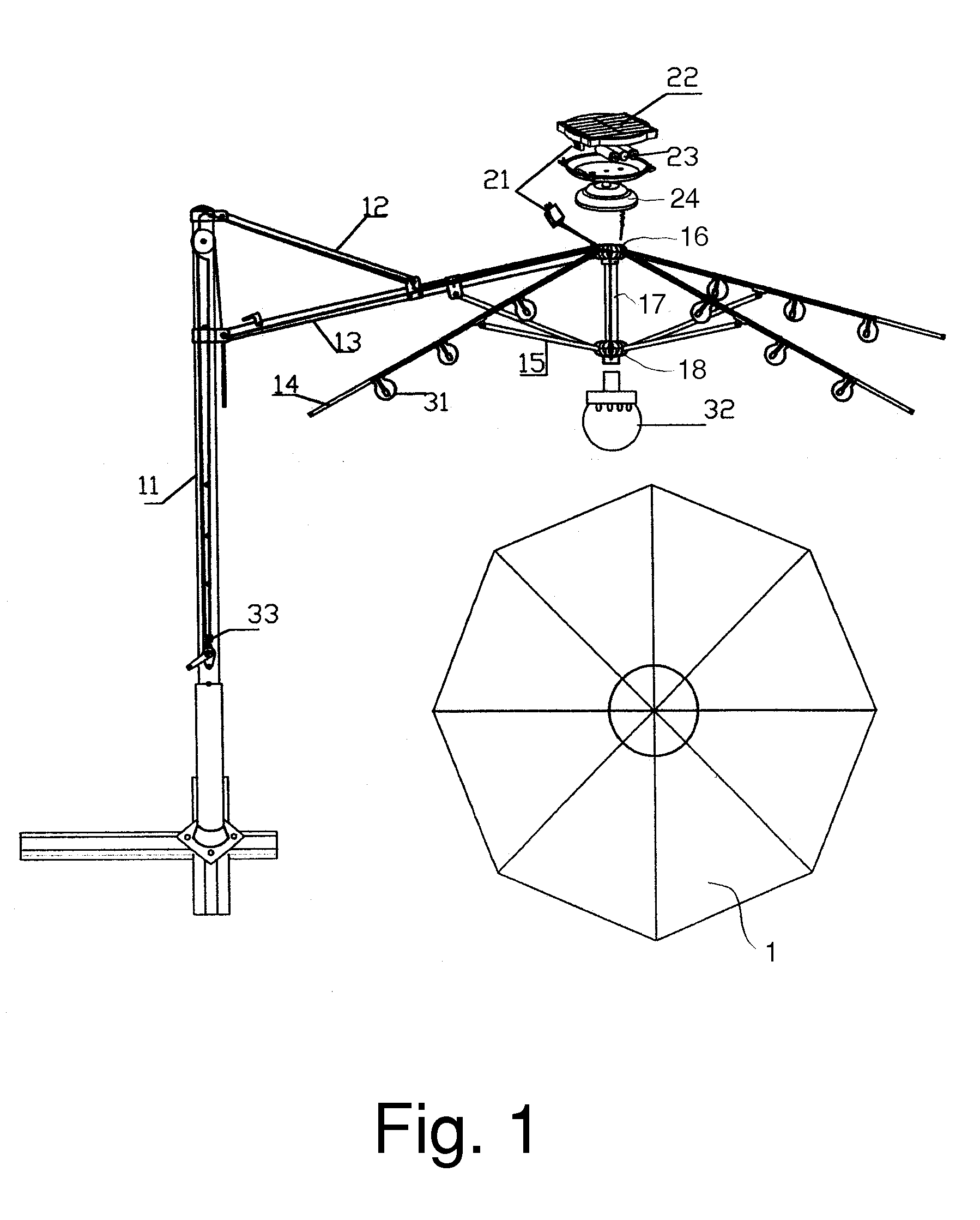
[0027] Referring to FIG.1, an illuminating device in accordance with the present invention is attached to a sunshade that generally comprises a biased-arranging post 11; a rib-mounting member 16 on top of a centrally positioned short pole 17; a plurality of ribs 14 each having an end pivotally connected to the rib-mounting member 16, which is fixed at the top position of the central short pole 17; a runner 18 slide-ably mounted to lower place of the centrally positioned short pole 17 underneath the canopy; a plurality of stretchers 15 each having a lower end pivotally connected to the runner 18 and upper end pivotally connected to an intermediate portion of an associated one of the ribs 14.

[0028] The sunshade has a biased-arranging post 11 for providing a non-obstacle central-positioned main illuminating area, and has a cantilever member 13 for supporting the canopy assembly. A pulling bar 12 having a collar slide-ably engaged on the cantilever member 13 maintains cantilever member...


PUM


Abstract

The present invention relates to a sunshade with an illuminating device including a biased-arranging post and a canopy assembly having a upright central short pole (17) carrying a rib-mounting member, a runner, electric wiring and winding line; the rib-mounting member (16) mounted on top of a central short pole (17); a plurality of ribs (14) each having an upper end hinged on the rib-mounting member (16); a runner (18) slide-ably mounted on the central short pole (17) of the canopy assembly; a plurality of stretchers (15) each having an upper end pivotally connected to an intermediate portion of an associated rib and a lower end pivotally connected to the runner (18); a fabric covering surface supported by a plurality of ribs (14) forming a canopy of umbrella. An automated opening and closing system includes a motor, a transmission, a line-winding shaft, a pulley system, and a cable system; a pulley system is coupled to an electric motor, a switch (33) is electrically connected between a power-supply unit (22) and an electric motor; a main light member (32) is fixed at the bottom end of the central positioned short pole (17) of the canopy and energized by a self-contained power source. A cantilever connects with the biased post (11) as a radius rod suspends and supports the canopy assembly.

Description

CROSS REFERENCE TO THE RELATED PATENT APPLICATION [0001] This patent application claims the priority benefit of the Chinese patent application No. 200520102570.8, filed on May 27, 2005. BACKGROUND OF THE INVENTION [0002] 1. Field of the Invention [0003] The present invention relates to a sunshade with an illuminating device for providing outdoor illumination. [0004] 2. Description of the Related Art [0005] A sunshade for shielding people from sunlight is thus widely used in outdoor café and rest areas as well as on beaches. [0006] An illuminating device is attached to a sunshade for the illumination purpose. The illuminating device needs a long-extended wiring connecting to an indoor socket or a generator for power supply. However, to use generator or long-extended wiring for supplying electricity in outdoor, some times brings big troubles. [0007] Currently used conventional sunshade with illumination has a defect that due to a canopy post erects on the ground in the central positio...

Claims


Application Information

Patent Timeline
IPC IPC(8): E04H15/10
CPCA45B2200/1027A45B3/04
Inventor WU, WEIDAN
Owner WU WEIDAN
Learn More