
Control of brake noise by tuned mass dampers

a technology of tuned mass and damper, which is applied in the direction of noise/vibration control, slack adjuster, braking elements, etc., can solve the problems of increasing the amplitude of the new system's vibration, the squeal of the brake, and the objectionable noise of the fixed and floating caliper disc brake system, so as to dampen the noise producing vibration of the drum brake shoe and the noise producing vibration of the disc brake pad

Inactive Publication Date: 2006-11-30
MATERIAL SCIENCES CORPORATION
View PDF13 Cites 40 Cited by
  • Summary
  • Abstract
  • Description
  • Claims
  • Application Information

AI Technical Summary

Benefits of technology

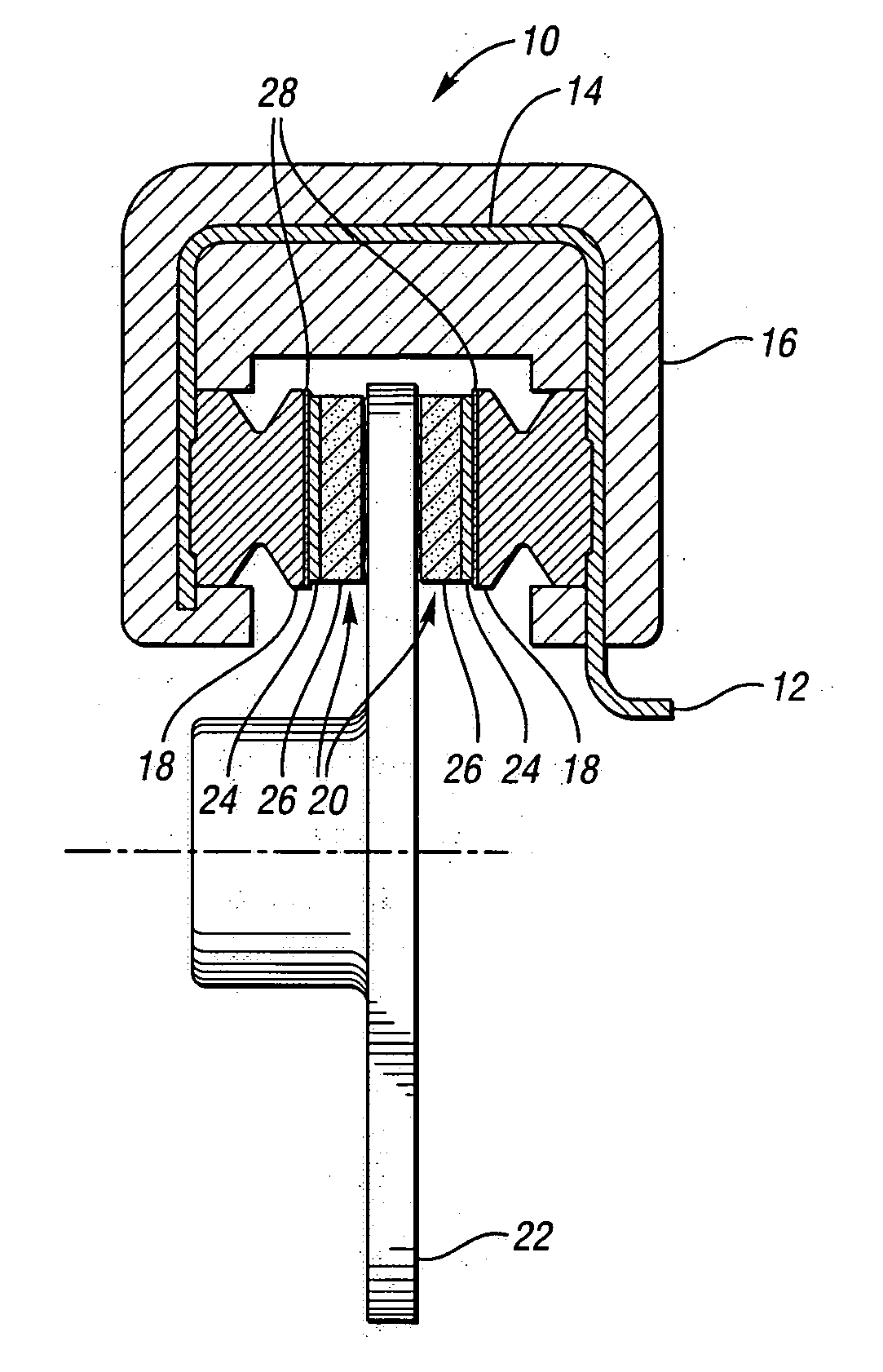
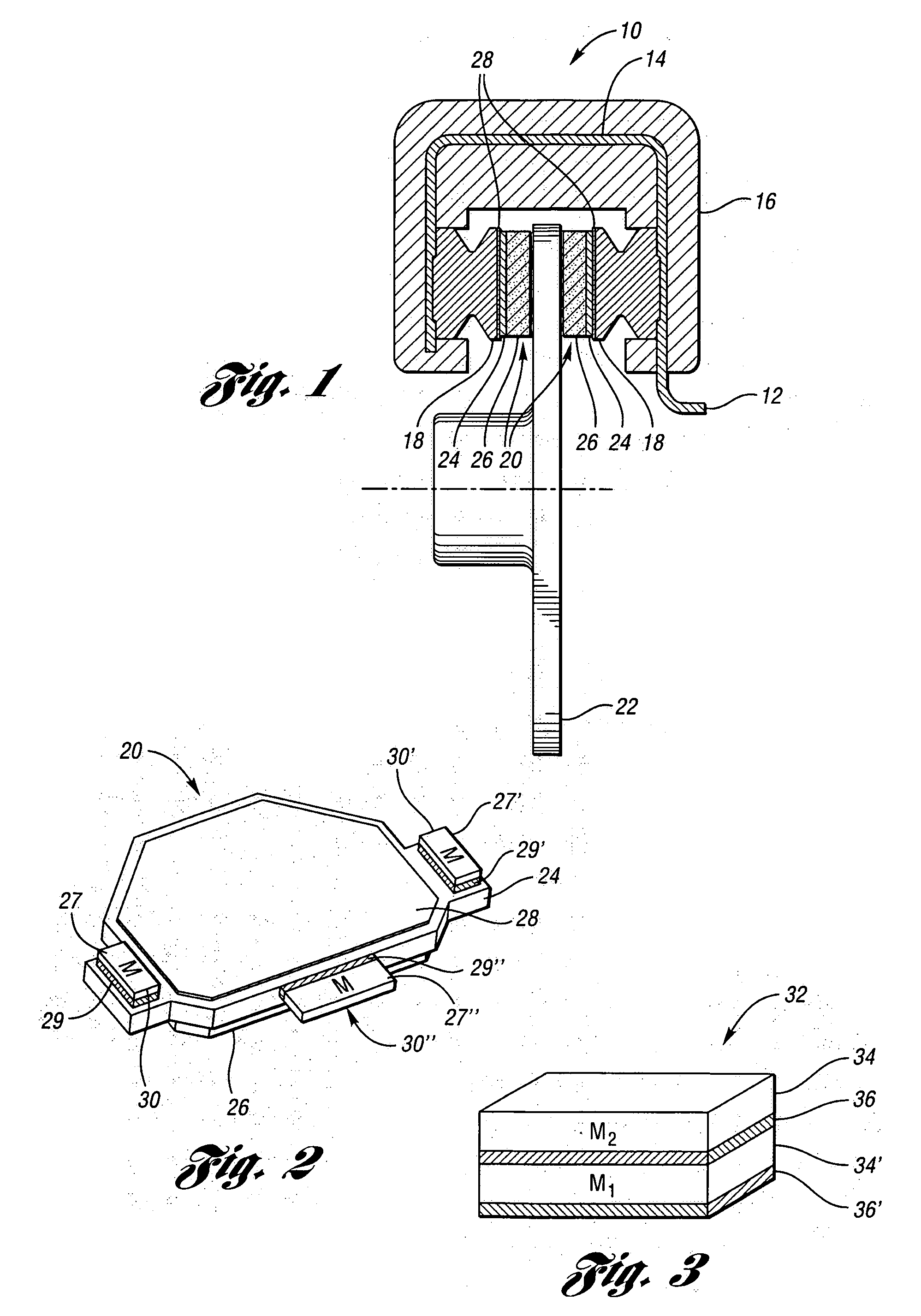
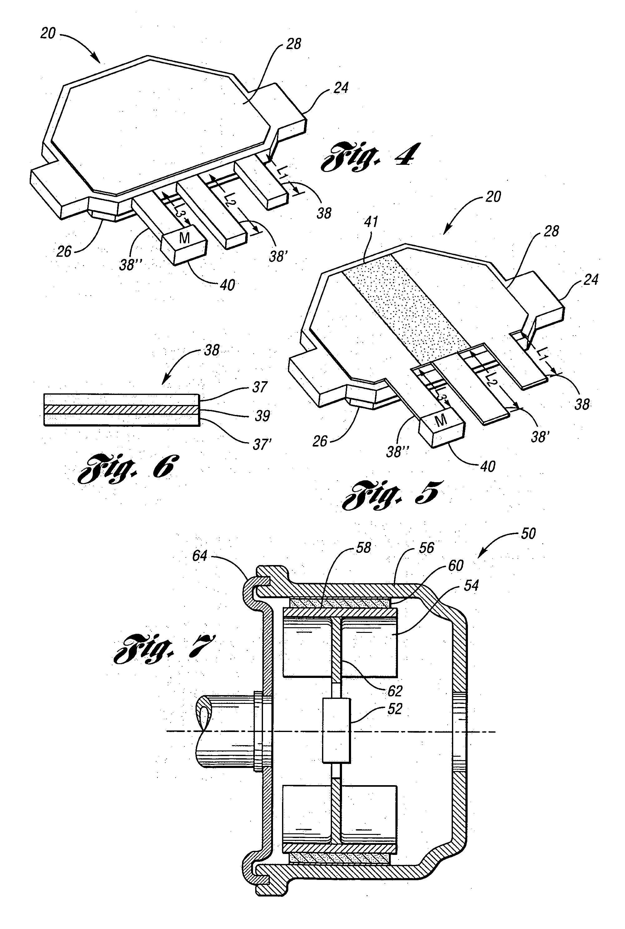
[0013] Accordingly, the present invention damps the noise producing vibrations of a disc brake pad by affixing to the brake pad and / or damping plate a tuned mass damper (TMD) of various configurations. The present invention can also damp the noise producing vibrations of a drum brake shoe and drum brake backplate by mounting a tuned mass damper to one or both of the aforementioned drum brake components.
[0019] The “dual modetuned mass damper has secondary mass and viscoelastic layer affixed atop a primary mass and viscoelastic layer. The type of materials and geometries for the “dual mode” tuned mass damper is application dependant. However, to be effective, the viscoelastic element with the highest modulus should be placed on the bottom of the stack, closest to the surface of the host structure. “Dual mode” tuned mass dampers increase the effectiveness of operation over a temperature range while attenuating more than one resonant frequency of the host structure.
[0024] Any of the previously mentioned tuned mass dampers may be used separately from, or in conjunction with, each other to achieve the desired level of vibration damping within the braking system. The preferred placement of the tuned mass damper will be the point of maximum amplitude of vibration, which is the position where the tuned mass damper is most effective.
[0028] The tuned mass damper may also be a beam formed from a constrained layer viscoelastic laminate material having at least two constraining layers, and at least one viscoelastic core disposed therebetween. This “beam type” tuned mass damper may be affixed to at least one of the first and second brake members and is operable to damp the vibrational kinetic energy occasioned by the brake member upon which it is mounted. The beam may also have a secondary mass affixed at any point along the beam to increase the modal mass of the tuned mass damper.

Problems solved by technology

Both fixed and floating caliper disc brake systems may suffer from an objectionable noise termed “brake squeal” when a braking force is applied.
If the level of damping in the new system is lower than necessary to dissipate the input energy from the friction forces during braking, the amplitude of vibration of the new system will increase until the system becomes unstable leading to “brake squeal”.
Since both the rotor and pad are vibrating together in-phase, the addition of damping to either component will tend to damp the system.
However, due to the high temperature of the rotor in operation, many of the applications have been limited to adding damping to the pad.
This active damping system may be more costly to implement than that of a passive system, and may not be economically viable for large-scale use on commercially produced vehicles.
Although constrained layer damping treatments have been found to be effective, in most cases there is still a need to introduce additional damping to the system.
Because of the spatial limitations of the disc brake system, this cannot be done with thicker constrained treatments.
The operation of a drum brake system may result in noise producing vibrations of the brake shoes, which may subsequently radiate to other elements of the drum brake system This is an undesirable phenomenon since these vibrations may result in the production of “brake squeal” that may be further amplified by the backplate of the drum brake system.
This backplate may act as a soundboard and cause a marginal “brake squeal” to become unacceptable.
This device may serve to damp the vibrations of the brake shoe, however modern brakes typically employ a “star wheel” adjuster in place of the abutment, thereby making the device difficult to implement in certain drum brake systems.

Method used


Image

  • Control of brake noise by tuned mass dampers
  • Control of brake noise by tuned mass dampers
  • Control of brake noise by tuned mass dampers

Examples


Embodiment Construction

[0043] The following description of the preferred embodiments should not be construed to limit the invention. For purposes of clarity, the same reference numbers will be used within the several figures to identify similar elements.

[0044] The present invention damps the noise producing vibrations of a disc brake pad by affixing to the backing plate of the brake pad or the damping plate a tuned mass damper (TMD) of various configurations. The present invention can also damp the noise producing vibrations of a drum brake shoe and drum brake backplate by mounting a tuned mass damper to one or both of the aforementioned drum brake components.

[0045] In its basic form, a tuned mass damper consists of a mass on a spring. The mass and stiffness of the spring are chosen so that they will have a resonance at a desired frequency. Applying such a system to a vibrating host structure having the same or slightly higher resonant frequency will cause the mass of the damper to move 180 degrees out-...


PUM


Abstract

This invention relates to the braking system of a vehicle and a method to attenuate noise-producing vibrations of components of the braking system by the use of tuned mass dampers of various designs mounted with respect to the brake pads and / or damper plate of a disc brake system. In another embodiment, the tuned mass dampers are attached to the brake shoes and / or drum brake backplate of a drum brake system.

Description

TECHNICAL FIELD [0001] This invention relates to the braking system of a vehicle and a method to attenuate noise by the use of tuned mass dampers mounted in relation to the brake pads, brake shoes, and / or drum brake backplate. BACKGROUND OF THE INVENTION [0002] Modern automotive braking systems may be grouped into two basic categories, disc brakes and drum brakes. Of the two systems, disc brakes offer higher performance, simpler design, lighter weight, self-adjustability, and better resistance to water interference. Drum brakes have a greater number of parts than disc brakes and are therefore more difficult to service, but they are less expensive to manufacture, can easily incorporate an emergency brake system, and provide adequate braking force. For the foregoing reasons, manufacturers tend to favor the use of drum brakes at the rear wheels of most modern automobiles. [0003] When a forward-moving vehicle brakes, the pitching motion of the vehicle creates a dynamic shift in the vehi...

Claims


Application Information

Patent Timeline
IPC IPC(8): F16D65/38
CPCF16D65/0012
Inventor DENYS, ERICNASHIF, AHID
Owner MATERIAL SCIENCES CORPORATION
Learn More