Multi-Transistor Layout Capable Of Saving Area
- Summary
- Abstract
- Description
- Claims
- Application Information
AI Technical Summary
Benefits of technology
Problems solved by technology
Method used
Image
Examples
Embodiment Construction
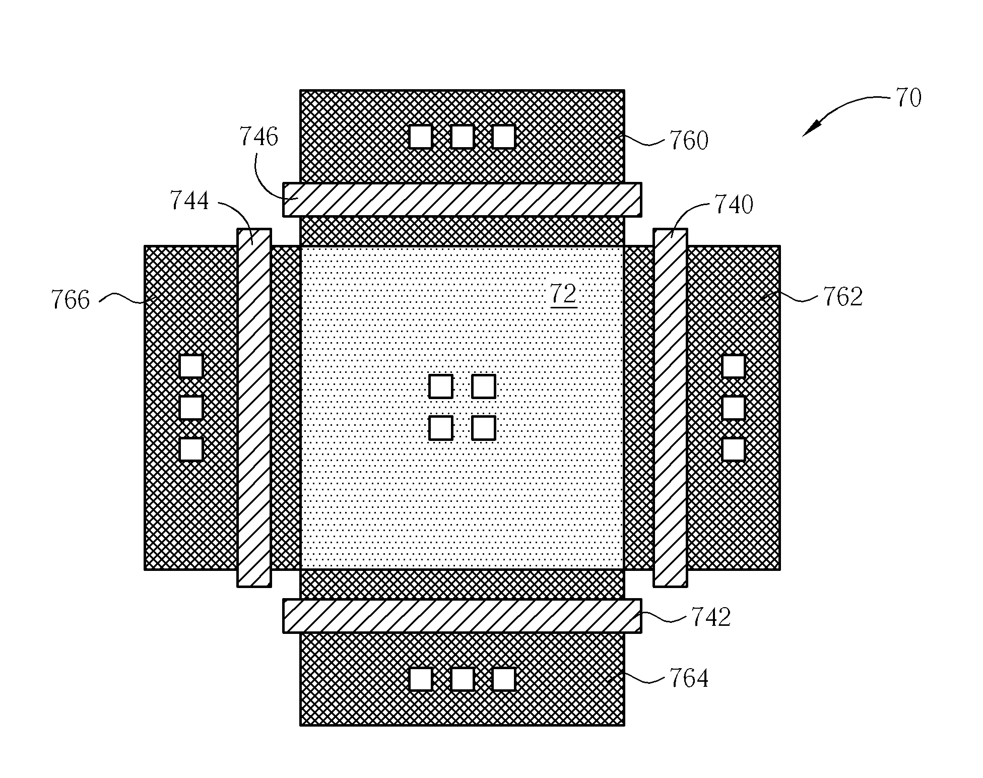
[0025] Please refer to FIG. 7, which illustrates a schematic diagram of a multi-transistor layout 70 in accordance with the present invention. The multi-transistor layout 70 includes a common drain 72, gates 740, 742, 744, 746, and sources 760, 762, 764, 766. The common drain 72 includes four contacts, each of the gates 740, 742, 744, and 746 includes one contact, and each of the sources 760, 762, 764, and 766 includes three contacts. If a minimum acceptable width of a drain is 4 μm and areas of the contacts on the common drain 72 are considered, a drain of a transistor in the multi-transistor layout 70 occupies an area of 7.02 μm2 (=5.3 μm×5.3 μm×0.25, where “0.25” means that four transistors share one drain). Therefore, the area of each drain in the present invention multi-transistor layout 70 is 31% of that in the multi-transistor layout 30. That is, for the same ESD rule, in a fixed area, the present invention multi-transistor layout 70 can save area and can be applied for a cir...
PUM
 Abstract
Description
Claims
Application Information
 - R&D
- Intellectual Property
- Life Sciences
- Materials
- Tech Scout
- Unparalleled Data Quality
- Higher Quality Content
- 60% Fewer Hallucinations
Browse by: Latest US Patents, China's latest patents, Technical Efficacy Thesaurus, Application Domain, Technology Topic, Popular Technical Reports.
© 2025 PatSnap. All rights reserved.Legal|Privacy policy|Modern Slavery Act Transparency Statement|Sitemap|About US| Contact US: help@patsnap.com


