Analog phase shifter using cascaded voltage tunable capacitor

a voltage variable capacitor and analog phase shifter technology, applied in delay lines, waveguide devices, waveguide types, etc., can solve the problem of inconsequential devices, reduce circuit layout size, reduce complexity, and simplify direct current control biasing

Active Publication Date: 2006-11-30
PHYSICAL OPTICS CORP
View PDF3 Cites 13 Cited by
  • Summary
  • Abstract
  • Description
  • Claims
  • Application Information

AI Technical Summary

Benefits of technology

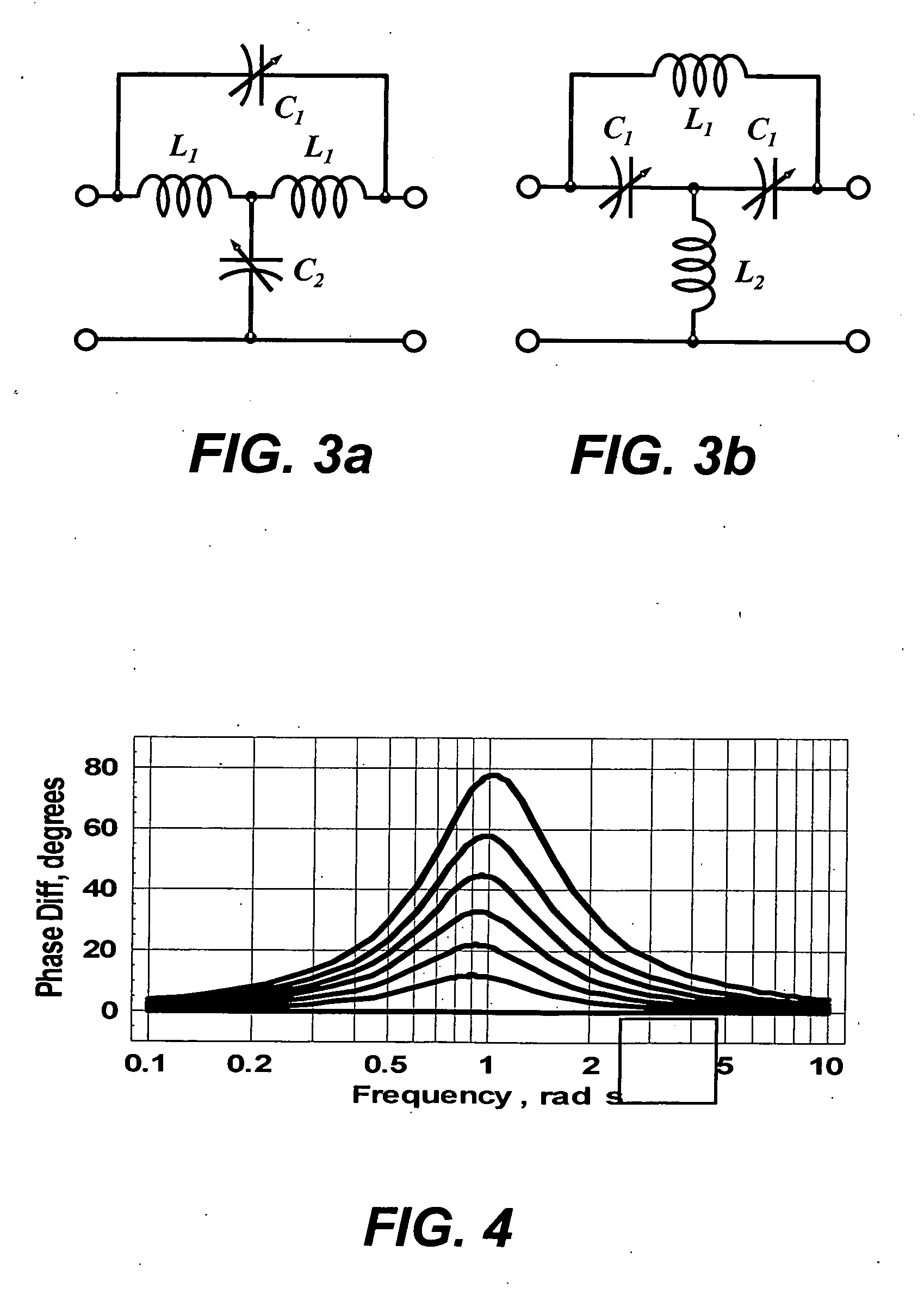
[0017] The circuit topology beneficially provides compact and broadband phase-shifters for phased-arrays using tunable capacitors. In one embodiment, the circuit topology provides a phase-shift to an RF signal over a desired range of frequencies. An advantage of the circuit topology is a flat phase versus frequency response over a wide range of frequencies. Further, the circuit topology also includes an advantage of little amplitude modulation over the frequency range and the bias states of the device. Moreover, the circuit topology can be configured as a device having a suitably small size.
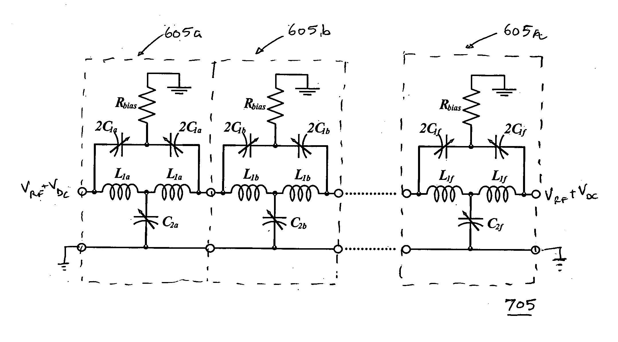
[0019] In addition, the circuit topology may include a DC biasing circuit. Generally, a composite phase-shifter has numerous tunable capacitors so that direct current (DC) control biasing becomes complicated if control wires are run to each tunable capacitor. Thus, in one embodiment, capacitors and inductors are preferably connected so that all sections can be biased from a single DC control line that is resistively coupled to the input or output. This configuration beneficially reduces complexity and may provide other benefits such as reduced circuit layout size, which would allow for smaller device sizes.

Problems solved by technology

A conventional phase shifter with a single all-pass circuit does not provide greater than a 90-degree phase shift so such a device is inconsequential for configurations requiring a large phase-shift.
However, due to conventional manufacturing and mechanical tolerances and errors in some instances more than a 360-degree phase shift is required, for example, a phase shift of up to 400-degrees.

Method used


Image

  • Analog phase shifter using cascaded voltage tunable capacitor
  • Analog phase shifter using cascaded voltage tunable capacitor
  • Analog phase shifter using cascaded voltage tunable capacitor

Examples


Embodiment Construction

[0035] The Figures (“FIGS.”) and the following description relate to preferred embodiments of the present invention by way of illustration only. It should be noted that from the following discussion, alternative embodiments of the structures and methods disclosed herein will be readily recognized as viable alternatives that may be employed without departing from the principles of the claimed invention.

[0036] Reference will now be made in detail to several embodiments of the present invention(s), examples of which are illustrated in the accompanying figures. It is noted that wherever practicable similar or like reference numbers may be used in the figures and may indicate similar or like functionality. The figures depict embodiments of the present invention for purposes of illustration only. One skilled in the art will readily recognize from the following description that alternative embodiments of the structures and methods illustrated herein may be employed without departing from ...


PUM


Abstract

A circuit topology is configured to flatten out a phase- and amplitude-response over a specified range of frequencies. The circuit topology also provides a large cumulative phase-shift. In one embodiment, the circuit topology cascades a plurality of all-pass sections, with the center-frequencies of each all-pass section staggered to create a substantially flat phase-response over a frequency range. Further, in one embodiment the plurality of all-pass sections has at least one all-pass section that is different from another all-pass section. Each all-pass section includes a tunable capacitor and has a center-frequency that can be varied by electronically tuning the capacitor. Each center frequency is selected to obtain substantially constant amplitude and phase response over a desired frequency range and capacitance tuning range.

Description

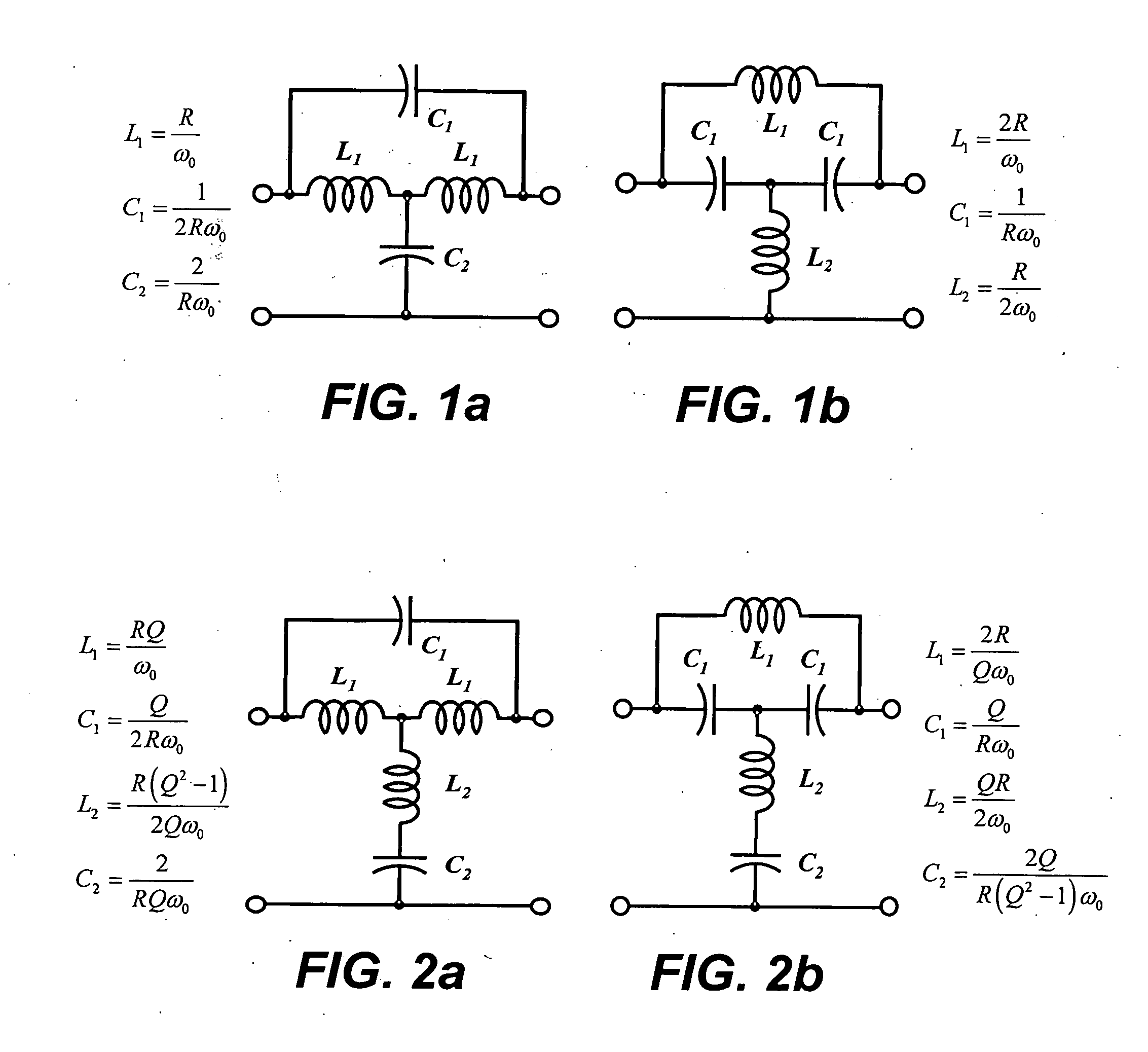
CROSS REFERENCE TO RELATED APPLICATIONS [0001] This application claims a benefit of, and priority under 35 USC § 119(e) to, U.S. Provisional Patent Application No. 60 / 690,452, filed Jun. 13, 2005, titled “Analog Phase Shifters Using Voltage-Tunable Capacitors”, and U.S. Provisional Application No. 60 / 686,100, filed May 31, 2005, titled “Broadband and Compact Analog Phase-Shifters Using Voltage-Tunable Capacitors,” the contents of both applications which are herein incorporated by reference.BACKGROUND OF THE INVENTION [0002] 1. Field of the Invention [0003] The present invention generally relates to the field of analog phase shifters and more specifically, to analog phase shifters using voltage variable capacitors. [0004] 2. Description of the Related Art [0005] All-pass networks are used in communication electronics for phase-compensation and phase-shifting networks. The transfer function for a simple fourth-order all-pass network has the form H⁡(ω)=ω2+a⁢ ⁢j⁢ ⁢ω-b2ω2-a⁢ ⁢j⁢ ⁢ω-b2(1...

Claims


Application Information

Patent Timeline
Patent Type & Authority Applications(United States)
IPC IPC(8): H03H7/18
CPCH03H7/20
Inventor YORK, ROBERT A.
Owner PHYSICAL OPTICS CORP
Why Eureka
Try Eureka