Back light, light guiding plate, method for manufacturing diffusion plate and light guiding plate, and liquid crystal display device

a technology of light guide plate and light guide plate, which is applied in the direction of light guide plate, lighting and heating apparatus, planar/plate-like light guide, etc., can solve the problems of mirror-like glare on the display screen, and achieve the effect of reducing parts count, simple method, and reducing parts coun

Inactive Publication Date: 2006-11-30
SONY CORP
View PDF31 Cites 51 Cited by
  • Summary
  • Abstract
  • Description
  • Claims
  • Application Information

AI Technical Summary

Benefits of technology

[0066] According to a first aspect of the present invention, in a liquid crystal display apparatus, a liquid crystal display device can be illuminated, particularly, with a reduced parts count, and satisfying a required light distribution performance.
[0067] According to a second aspect of the present invention, a diffuser can be manufactured. Particularly, a diffuser in which the diffusion layer and the light distribution layer are integrally formed can be manufactured with a simple method, using multi-layer extrusion molding and rolling.
[0068] According to a third aspect of the present invention, a diffuser can be manufactured. Particularly, a diffuser in which the light focusing layer, the diffusion layer, and the light distribution layer are integrally formed can be manufactured with a simple method, using multi-layered extrusion molding and rolling.
[...

Problems solved by technology

However, by using the lens film in order to increase display luminance, moire may occur on the display screen due to interference bet...

Method used


Image

  • Back light, light guiding plate, method for manufacturing diffusion plate and light guiding plate, and liquid crystal display device
  • Back light, light guiding plate, method for manufacturing diffusion plate and light guiding plate, and liquid crystal display device
  • Back light, light guiding plate, method for manufacturing diffusion plate and light guiding plate, and liquid crystal display device

Examples


embodiment 1

[Embodiment 1]

[0107] A first embodiment of the present invention will be described below with reference to the drawings.

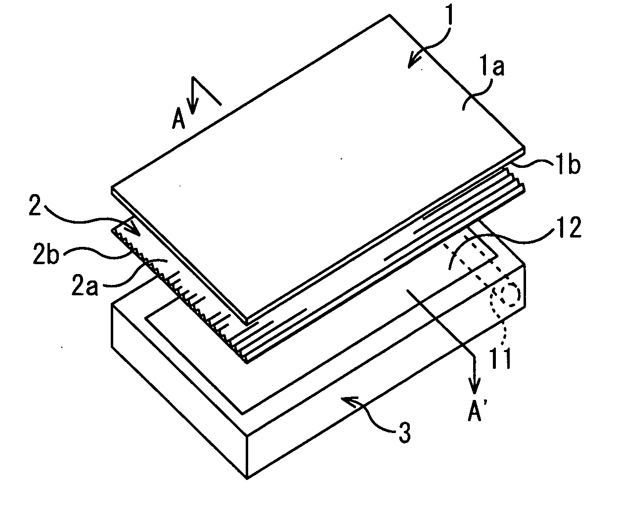
[0108] Backlights come in a type wherein a light source such as a cold cathode fluorescent light (CCFL) or a light emission diode (LED) is arranged along and in proximity to a side surface of a light guide plate formed from a transparent synthetic resin plate for guiding light, and a type wherein light sources such as a plurality of cold cathode fluorescent lights are arrayed in parallel with each other. A diffuser for diffusing light for uniform emission onto the liquid crystal display device is interposed, in the former, between the light guide plate and the liquid crystal display device, and, in the latter, between the plurality of cold cathode fluorescent lights and the liquid crystal display device.

[0109] In Embodiment 1, a description will be given of a case where light sources such as a plurality of cold cathode fluorescent lights are arrayed in parallel w...

embodiment 2

[Embodiment 2]

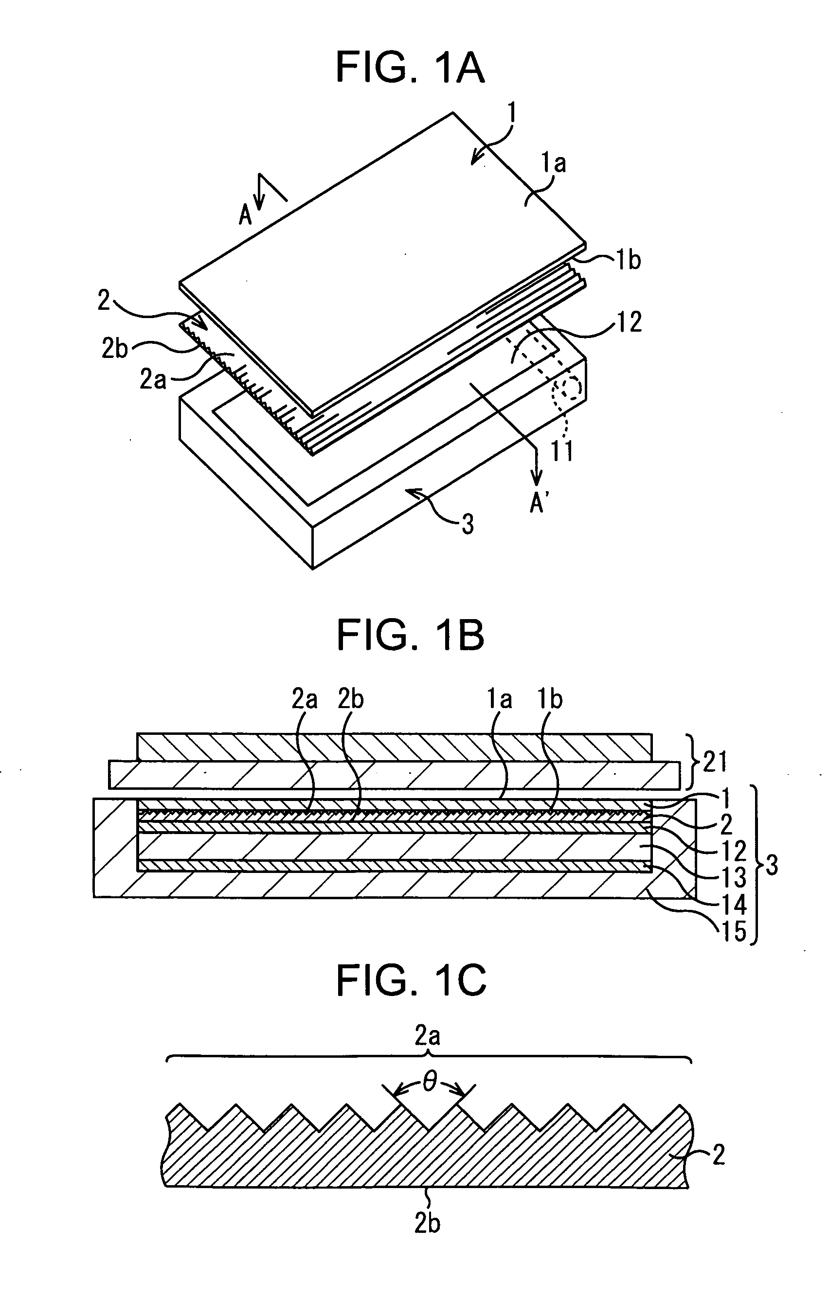
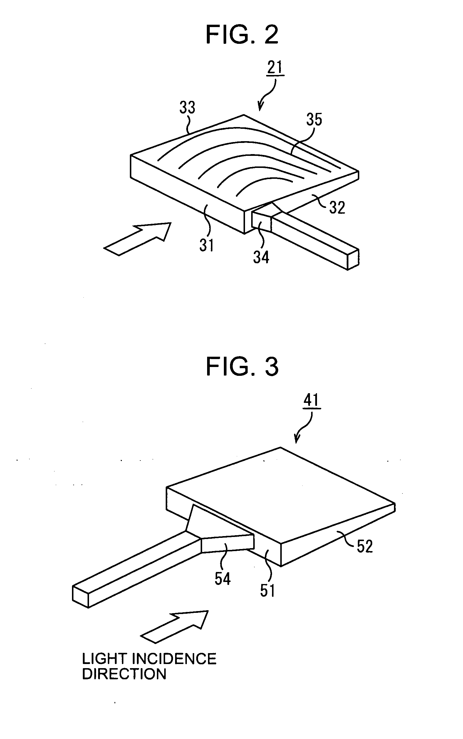
[0177] Next, the best mode for carrying out a light guide plate according to the present invention, and a method of manufacturing the light guide plate and a backlight according to the present invention, will be described in detail with reference to the drawings.

[0178] Likewise in the case of Embodiment 1 mentioned above, backlights come in a type wherein light sources such as a plurality of cold cathode fluorescent lights are arrayed in parallel with each other immediately below a liquid crystal display device, and a type wherein a light source such as a cold cathode fluorescent light (CCFL) or a light emission diode (LED) is arranged along and in proximity to a side surface of a light guide plate formed from a transparent synthetic resin plate for guiding light. In Embodiment 2, a case where a light source such as a light emitting diode is disposed along and in proximity to a side surface of a light guide plate formed from a transparent synthetic resin plate for gui...


PUM


Abstract

The present invention relates to a backlight and a light guide plate, a method of manufacturing a diffuser and the light guide plate, and to a liquid crystal display apparatus, all enabling a cost reduction by reducing the parts count and curtailing unnecessary manufacturing processing. A diffuser 261 has a light distribution layer 181 including a prismatic surface wherein stripe grooves or asperities are arrayed in parallel with each other, a diffusion layer 182 containing diffusion elements 191 for diffusing incident light, and a light incidence control layer 271 including a prismatic surface wherein stripe grooves or asperities are arrayed in parallel on a side of fluorescent tubes 131. The diffusion layer 182 is formed from the same resin, and only the diffusion elements 191 are formed from a different resin. The prism of the light incidence control layer 271 is optimized so as to enhance the proportion, to light being reflected without entering the light incidence control layer 271, of light re-entering other parts of a surface of the light incidence control layer 271, in order to guide incident light toward the diffusion layer 182 efficiently. The present invention is applicable to a backlight of a liquid crystal display apparatus.

Description

TECHNICAL FIELD [0001] The present invention relates to a backlight and a light guide plate, a method of manufacturing a diffuser and the light guide plate, and to a liquid crystal display apparatus. Particularly, it is directed to a backlight and a light guide plate, a method of manufacturing a diffuser and the light guide plate, and to a liquid crystal display apparatus, all enabling a cost reduction by reducing the parts count and curtailing unnecessary manufacturing processing. BACKGROUND ART [0002] A liquid crystal display apparatus includes: a liquid crystal display device (called also an LCD panel) wherein two transparent glass substrates are stacked in alignment one upon another such that surfaces thereof, each having transparent electrodes, an alignment film, and the like laminated thereon, face to each other, and wherein liquid crystal is sealed between both substrates; a backlight, disposed below the liquid crystal display device, for supplying light to the liquid crystal...

Claims


Application Information

Patent Timeline
IPC IPC(8): A47F3/00F21V8/00G02B5/02G02B6/00G02F1/13357
CPCB29D11/00663G02B5/0242G02B5/0278G02B6/0013G02F2001/133607G02B6/0051G02B6/0053G02F1/133606G02F1/133611G02B6/0038G02F1/133607G02F1/1335
Inventor OKU, TAKASHIHATANAKA, MASATOKAWASHIMA, YOSHINARIKOSHIMURA, AKIRASHIRATORI, KAZUHIRO
Owner SONY CORP
Why Eureka
Try Eureka