Packet forwarding apparatus using token bucket algorithm and leaky bucket algorithm

Inactive Publication Date: 2006-11-30
HITACHI LTD
View PDF11 Cites 45 Cited by
  • Summary
  • Abstract
  • Description
  • Claims
  • Application Information

AI Technical Summary

Benefits of technology

[0011] According to the an aspect of this invention, there is provided a packet forwarding node for transmitting data and network system including an interface unit for sending and receiving packets, and a traffic shaper unit for controlling the packet transmission timing and a packet switch for sending an output to the interface unit as the destination of the received packet; and the traffic shape

Problems solved by technology

However in the related art, when the network became congested, users using empty band space to send data greater than the minimum frame rate were unable to send pack

Method used


Image

  • Packet forwarding apparatus using token bucket algorithm and leaky bucket algorithm
  • Packet forwarding apparatus using token bucket algorithm and leaky bucket algorithm
  • Packet forwarding apparatus using token bucket algorithm and leaky bucket algorithm

Examples


first embodiment

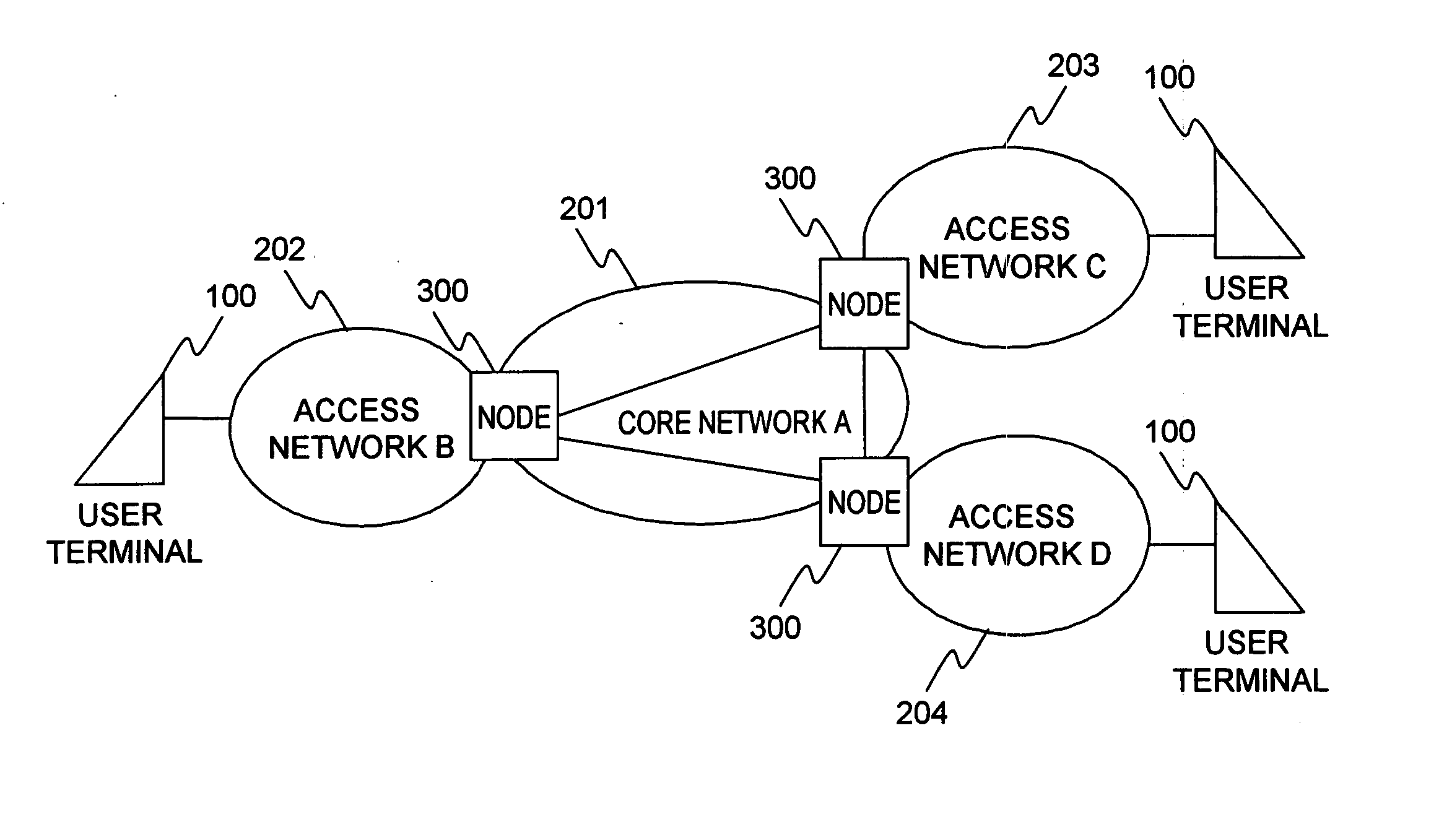
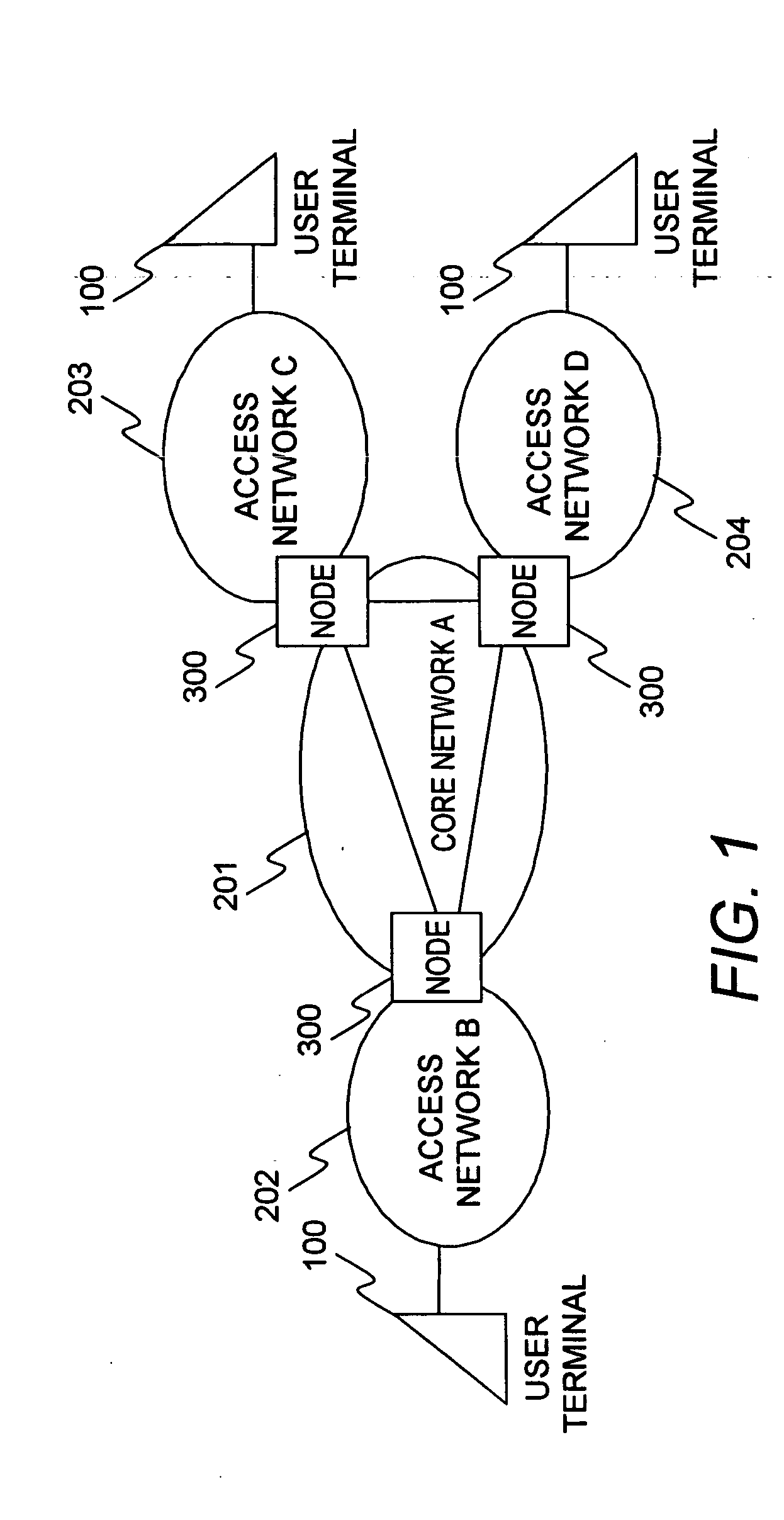
[0035]FIG. 1 is a concept view of the network system of the first embodiment of this invention.

[0036] The network system of the first embodiment includes a core network A201, an access network B202, an access network C203 and an access network D204. The core network A201 and the access networks B202 C203 and D204 are an optical fiber network.

[0037] A network node 300 connects the access network B202, access network C203 and the access network D204, with the core network A201. A user terminal 100 connects to the access networks B202 through D204.

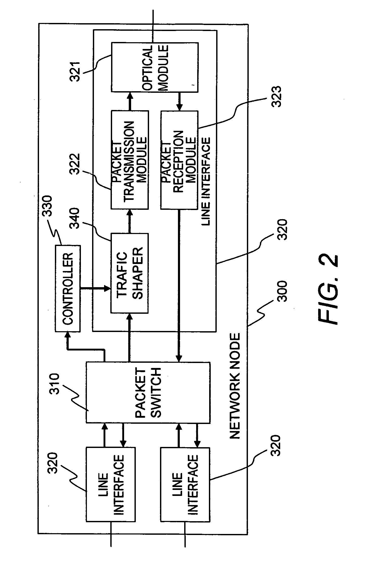
[0038]FIG. 2 is a block diagram of the network node 300 of the first embodiment of this invention.

[0039] The network node 300 includes a packet switch 310, multiple line interfaces 320 and controllers 330.

[0040] The packet switch 310 decides the destination of the packet that the line interface 320 received and sends received packet to the transmit line interface 320.

[0041] The line interface 320 includes an optical module 321, a packet...

second embodiment

[0170]FIG. 17 is a block diagram showing the network structure of the second embodiment of this invention of this invention.

[0171] The network of this embodiment of this invention, includes an Internet 1110, a telephone network (private line network) 1120, Optical Network Unit (ONU) 1200 and Optical Line Terminal (OLT) 1300.

[0172] The ONU 1200 is a terminating set for the subscriber side of the optical fiber network. The Ethernet and telephone lines (or private lines) installed on the subscriber side connect to the ONU 1200.

[0173] The ONU 1200 receives optical signals transmitted from the OLT 1300, and generates electrical signals by optical-electrical conversion. The ONU 1200 also multiplexes signals input from the Ethernet and telephone lines, and transmits them as optical signals at a timing specified from the OLT 1300.

[0174] The OLT 1300 is a terminating set on the station side of the optical fiber network. The OLT 1300 connects to the Internet 1110 and the telephone network...


PUM


Abstract

A packet forwarding apparatus and network system for providing different types of bandwidth control services to the user; in which a packet forwarding apparatus for transferring data comprises an interface unit for sending and receiving packets, and a traffic shaper for controlling the packet transmission timing and a packet switch for sending an output to the interface unit as the destination of the received packet; and the traffic shaper uses a token bucket algorithm when transmitting a packet to guarantee the minimum frame rate, and uses a leaky bucket algorithm when limiting the peak frame rate.

Description

CLAIM OF PRIORITY [0001] The present application claims priority from Japanese patent application P2005-154047 filed on May 26, 2005, the content of which is hereby incorporated by reference into this application. FIELD OF THE INVENTION [0002] The present invention relates to a packet forwarding node and relates in particular to bandwidth control technology ideal for packet forwarding nodes comprising an optical interface. BACKGROUND OF THE INVENTION [0003] Recent advances in network technology are creating a shift in network access away from narrow band access services such as dialup, and towards broadband access services such as FFTH (Fiber To The Home). Along with this shift, an increasing number of applications require real time operation (streaming, VoIP, net-banking, etc.) rather than applications (mail, World Wide Web, data transmission) that are not greatly affected by changes in communication bandwidth. The demand for a network with a stable communication bandwidth is incre...

Claims


Application Information

Patent Timeline
IPC IPC(8): H04L12/26H04L12/56H04L47/22H04L47/21H04L47/525
CPCH04L47/10H04L47/20H04L47/21H04Q2011/0064H04L47/22H04Q11/0067H04L47/215
Inventor TAKASE, MASAYUKIASHI, YOSHIHIROMIZUTANI, MASAHIKOKAZAWA, TOHRUSAKAMOTO, KENICHISHINAGAWA, TAISHI
Owner HITACHI LTD
Why Eureka
Try Eureka