System and method for dynamic control of ultrasonic magnetostrictive dental scaler

a dynamic control and ultrasonic magnetostrictive technology, applied in the field of dynamic control of ultrasonic magnetostrictive dental scalers, can solve the problems of inconvenient manual tuning of dental scalers, fragile wirings, interconnection of additional wires, etc., and achieve the effect of enhancing performance and greater control

Active Publication Date: 2006-11-30
RN HLDG LLC
View PDF25 Cites 28 Cited by
  • Summary
  • Abstract
  • Description
  • Claims
  • Application Information

AI Technical Summary

Benefits of technology

[0006] The present disclosure relates to a magnetostrictive ultrasonic dental scaler which includes a handpiece and dental scaler device having a control circuit which dynamically maintains a desired operating point under varying loads and operating conditions. The operating point may be directly on a resonance of the handpiece at a fixed frequency shift from the resonance. The control circuit enables a greater level of control and enhanced performance by use of dynamic tracking of resonance under variable loading. In particular, the control circuit includes a digital signal processor which processes sensed feedback signals regarding frequency and amplitude of vibrations and filters the signals through dynamic filter loops to obtain error and / or control signals to adjust the output of the dental scaler thereby controlling the frequency and amplitude of vibrations and arriving at the desired operating point.

Problems solved by technology

Manual tuning of the dental scaler is inconvenient, therefore, automatic frequency and amplitude tuning circuits have been developed.
However, these circuits suffer from a number of mechanical disadvantages (e.g., interconnection of additional wires, fragile wirings, placement of controls, etc.) and electronic disadvantages (e.g., inaccurate signal processing, interference, etc.).

Method used


Image

  • System and method for dynamic control of ultrasonic magnetostrictive dental scaler
  • System and method for dynamic control of ultrasonic magnetostrictive dental scaler

Examples


Embodiment Construction

[0013] Particular embodiments of the present disclosure are described hereinbelow with reference to the accompanying drawings. In the following description, well-known functions or constructions are not described in detail to avoid obscuring the present disclosure in unnecessary detail.

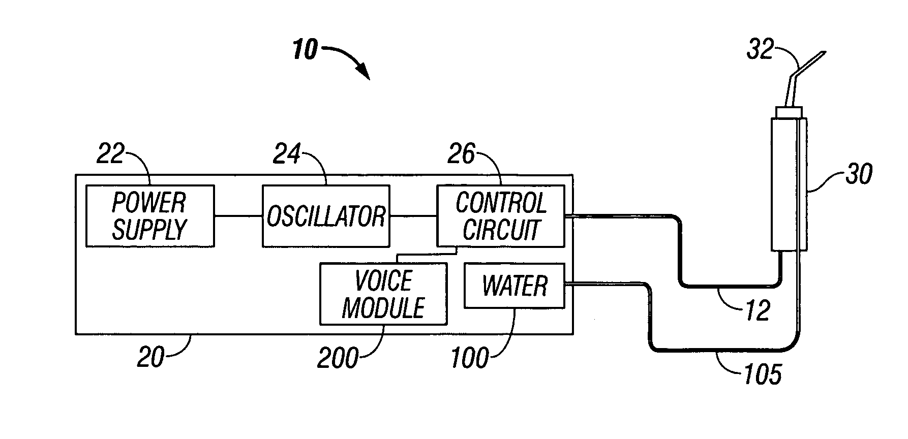
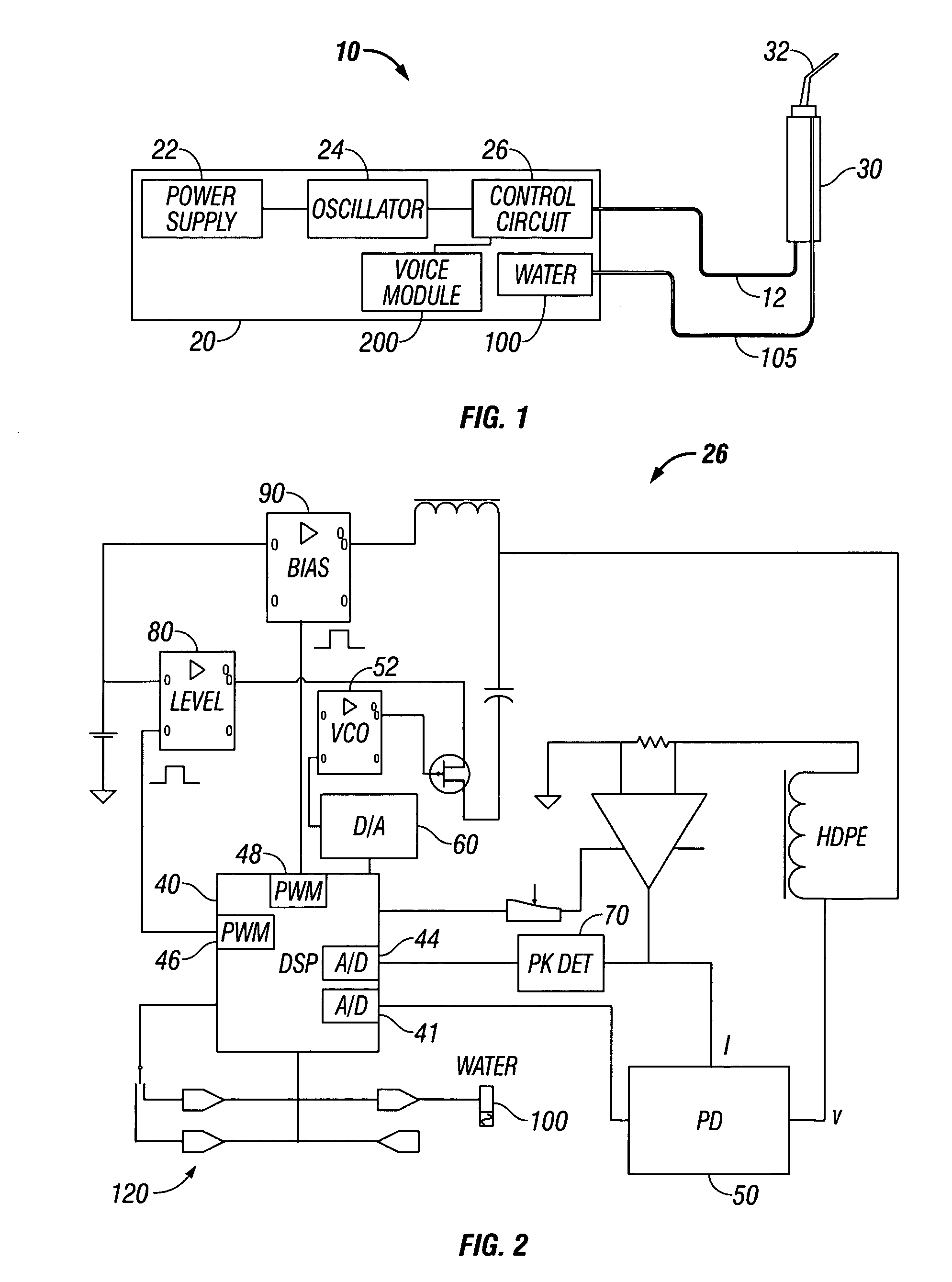
[0014]FIG. 1 shows a dental scaler system 10 including a dental scaler device 20 and a handpiece 30 connected to the scaler device 20 via a cable 12. The dental scaler device 20 includes a DC power supply 22, which may be either internal or external to the scaler device 20, an oscillator 24, and a control circuit 26. The DC power supply 22 provides voltage to the scaler device 20. This voltage is used to provide functionality to the scaler device 20 (e.g., indicator lights, switches, etc.) and to power the oscillator 24 which converts DC voltage into high frequency signals for energizing the handpiece 30.

[0015] The handpiece 30 includes a tip 32 and an energizing coil 34 which ultrasonically vibrate...


PUM


Abstract

A magnetostrictive ultrasonic dental scaler is disclosed. The magnetostrictive device comprises an oscillator adapted to provide electrical energy including a current and a voltage signal, a handpiece having a tool tip which vibrates in response to the electrical energy supplied to the handpiece and a control circuit. The control circuit includes a phase detector adapted to detect phase between current and voltage signals and to generate a phase detection signal as a function of the phase. The control circuit also includes a digital signal processor operatively connected to the phase detector. The digital signal processor adapted to process the phase detection signal through a digital loop filter to generate an error signal. The control circuit further includes a voltage controlled oscillator operatively connected to the digital signal processor, wherein the error signal outputs a voltage to operate the voltage controlled oscillator which in response thereto adjusts at least one of frequency and amplitude of vibrations of the tool tip.

Description

PRIORITY CLAIM [0001] The present application claims priority to a U.S. Provisional Application Serial No. 60 / 682,128 entitled “Operational Description of a New Ultrasonic Magnetostrictive Dental Scaler” filed by Richard Pachke et al. on May 18, 2005.BACKGROUND [0002] 1. Technical Field [0003] The present disclosure relates to a system and method for dynamically controlling frequency and amplitude settings of an ultrasonic magnetostrictive dental scaler. More particularly, the present disclosure relates to a system and method for utilizing digital filter control loops to individually adjust amplitude and frequency of the vibrations. [0004] 2. Background of Related Art [0005] Ultrasonic dental scalers are generally used to clean various types of build up from teeth. Dental scalers include a control circuit, a handpiece having an ultrasonic transducer, an energizing coil and a tool tip. In particular, the energizing coil actuates the transducer which then produces vibrational motion. ...

Claims


Application Information

Patent Timeline
Patent Type & Authority Applications(United States)
IPC IPC(8): A61C3/03
CPCA61C1/0015A61C17/20A61C1/07
Inventor PASCHKE, RICHARDPASCHKE, NOEL S.ROSE, EMERY S.
Owner RN HLDG LLC
Why Eureka
Try Eureka