
System and method for chatter stability prediction and control in simultaneous machining applications

a simultaneous machining and stability prediction technology, applied in the direction of process and machine control, process control, instruments, etc., can solve the problems of inability to assess the regenerative force of sm applications, the dynamic stability repercussions of such settings are poorly understood, and the dynamic stability of sm applications is considerably more complex, so as to reduce and/or control the chatter of machine tools and optimize the effect of machining utilities and applications

Inactive Publication Date: 2006-11-30
UNIV OF CONNECTICUT
View PDF32 Cites 30 Cited by
  • Summary
  • Abstract
  • Description
  • Claims
  • Application Information

AI Technical Summary

Benefits of technology

[0020] According to the present disclosure, advantageous systems and methods for optimization of SM machining operations and / or applications are disclosed. The SM applications encompassed within the disclosed systems and methods have particular applicability to systems that include multiple spindles and / or one or more single milling cutters with non-uniformly distributed cutter flutes, operating on a single workpiece. Indeed, the systems and methods of the present disclosure are effective in reducing and / or controlling machine tool chatter in simultaneous machining (SM) applications as defined herein, thereby permitting efficient and / or optimized machining utilities and applications.

Problems solved by technology

It is also known that the dynamics of SM applications are considerably more complex.
The dynamic stability repercussions of such settings are poorly understood at present, even in the mathematics community.
In fact, there is no analytical mechanism available to assess such regenerative forces in SM applications and no evidence in the literature addressing the stability of simultaneous machining.
It is well known from numerous investigations that conventional single tool machining (STM) introduces significant stability issues, e.g., when STM operations are optimized.
Stability issues are even more pronounced in more complex SM applications and systems.
Machine tool instability associated with machining applications primarily relates to ‘chatter’.
They are inapplicable, however, to SM because of the substantial differences in the underlying mathematics.
There is no practical methodology known at this point, to resolve the complete stability mapping for such constructs.
Machine tool chatter is an undesired engineering phenomenon.
Multiplicity of the delays present enormously more complicated problems compared with the conventional single-tool machining (STM) chatter and have heretofore prevented the mapping and / or control of SM applications for optimization purposes.
For instance, if the removal rate is increased (e.g., by increasing the chip width, b), chatter instability is ultimately encountered which is obviously undesirable and unacceptable.
The stability of multiple delay systems is poorly known in the mathematics community.
There is no simple extension of the conventional (STM) stability treatment to multiple spindle and / or non-uniformly distributed flutes on a single cutter, and consequently to multiple delay cases.
First, the foregoing investigations are performed point-by-point in (τ1,τ2) space and, therefore, the application is computationally overwhelming.
This approach imposes an obvious and very serious restriction for the problem at hand.
Further prior art teachings tackle a limited sub-class of equation (4) with detG(s) of degree 2, but without a damping term, and the disclosed approach is not expandable to damped cases.

Method used


Image

  • System and method for chatter stability prediction and control in simultaneous machining applications
  • System and method for chatter stability prediction and control in simultaneous machining applications
  • System and method for chatter stability prediction and control in simultaneous machining applications

Examples


case study ii

f CTCR Methodology to Single Tool Machining (STM)

[0083] For the conventional chatter stability study (with a single cutter, n=1), a regenerative dynamics with one single time delay appears. The characteristic equation (5) reduces to:

CE(s,τ,b)=a0(b,s)+a1(b,s)e−τs=0  (17)

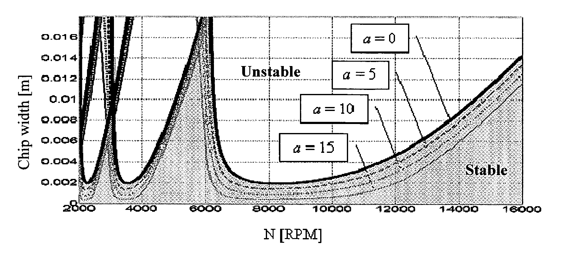
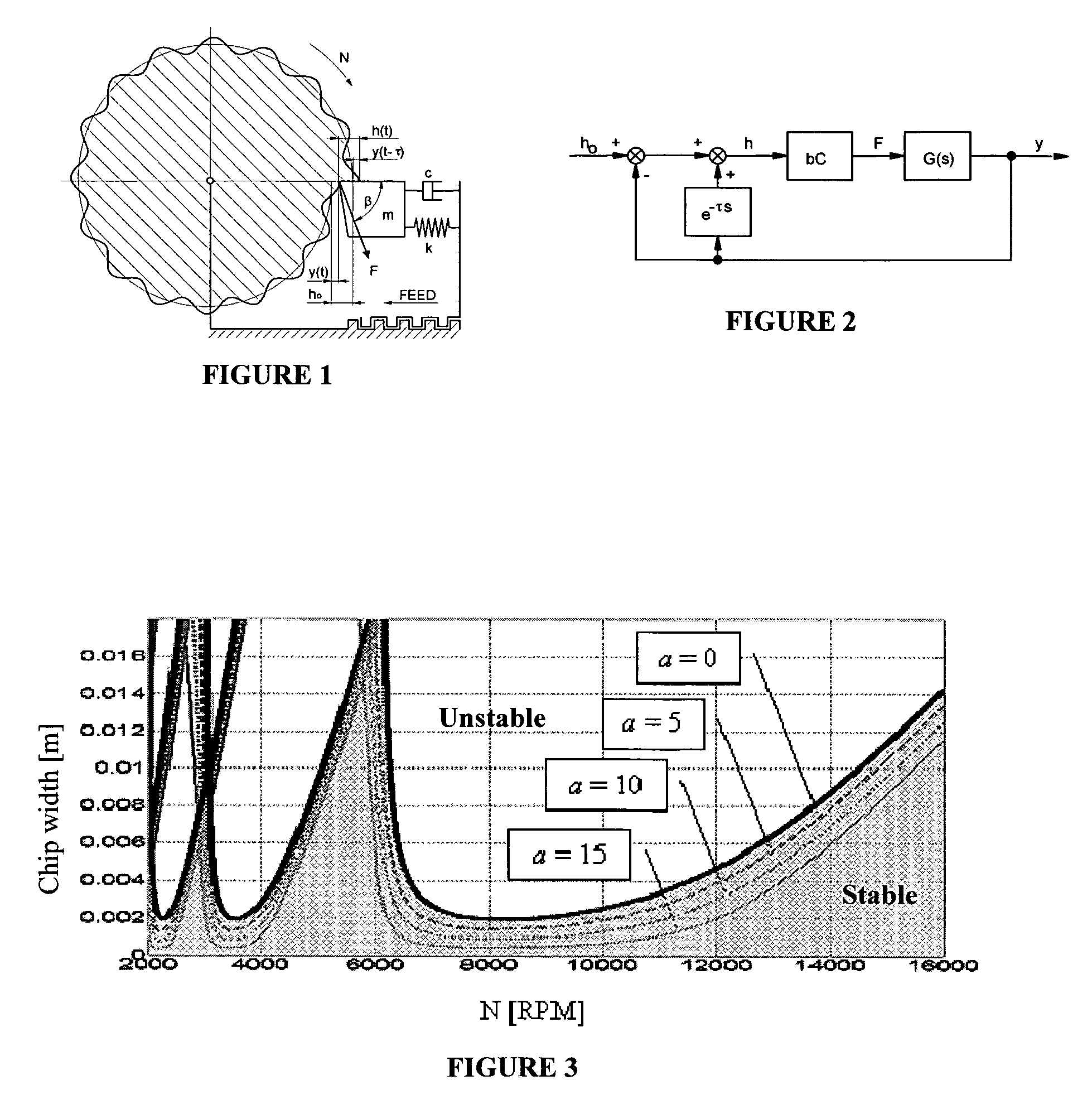
where the only delay is τ[sec]=60 / N[RPM], N is the spindle speed and b is the width-of-cut. There are numerous case studies in the literature on this problem. For demonstration purposes, orthogonal turning given in Equation 7 of a publication by Olgac et al. is studied [see, N. Olgac and M. Hosek, “A New Perspective and Analysis for Regenerative Machine Tool Chatter,”International Journal of Machine Tools &Manufacture, vol. 38, pp. 783-798, 1998], which starts from the characteristic equation: 1+bC⁢Cos⁢ ⁢β⁡(1-ⅇ-τ⁢ ⁢s)m⁢ ⁢s2+cs+k=0(18)

where b is the chip width, C, β, m, c and k are the constants related to the cutting dynamics. This equation can also be written as:

CE(s,τ,b)=ms2+cs+k+bC Cos β(1−e−τs)=0  (19)

whic...


PUM

PropertyMeasurementUnit
diameteraaaaaaaaaa
depthsaaaaaaaaaa
chatter frequenciesaaaaaaaaaa

Abstract

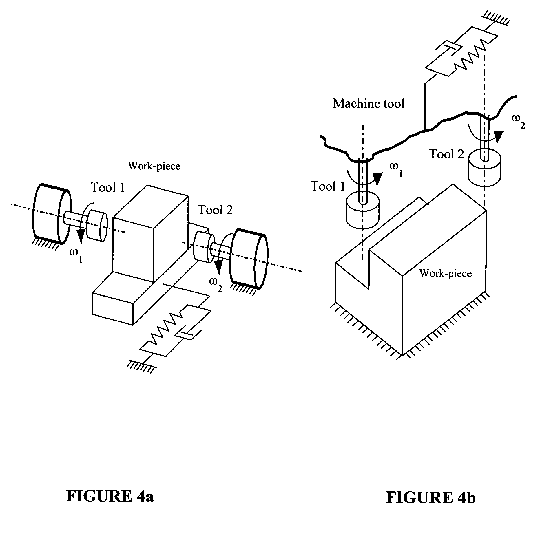
Systems and methods are provided for use in assessing the stability of simultaneous machining (SM) dynamics (which is also known as parallel machining). In SM, multiple cutters, which are generally driven by multiple spindles at different speeds, operate on the same work-piece. In an alternative implementation of SM, single milling cutters with non-uniformly distributed cutter flutes operate on a work-piece. When SM is optimized in the sense of maximizing the rate of metal removal constrained with or by the machined surface quality, “chatter instability” phenomenon appears. The present disclosure declares the complete stability picture of SM chatter within a mathematical framework of multiple time-delay systems (MTDS). A cluster treatment of characteristic roots (CTCR) procedure determines the regions of stability completely in the domain of the spindle speeds for varying chip thickness, thereby replicating the well-known “stability lobes” concept of STM for simultaneous machining.

Description

1. CROSS-REFERENCE TO RELATED APPLICATIONS [0001] The present application claims the benefit of a co-pending provisional patent application entitled “System and Method for Chatter Stability Prediction and Control in Simultaneous Machining Applications,” which was filed on May 26, 2005 and assigned Ser. No. 60 / 684,915. The entire contents of the foregoing provisional patent application are incorporated herein by reference.2. TECHNICAL FIELD [0002] The present disclosure is directed to an advantageous system and method for optimization of machining applications with multiple cutters on a single workpiece. More particularly, the present disclosure is directed to systems / methods for reducing and / or controlling machine tool chatter in simultaneous machining applications, thereby permitting efficient and / or optimized machining utilities and applications. 3. BACKGROUND ART [0003] The present application relates to the stability of simultaneous (or parallel) machining, where multiple tools ...

Claims


Application Information

Patent Timeline
Patent Type & Authority Applications(United States)
IPC IPC(8): B23Q11/00G06F19/00
CPCB23Q17/0976G05B19/404G05B2219/41256Y10T82/10Y10T409/303752Y10T82/2595Y10T409/304312G05B2219/50015
Inventor OLGAC, NEJAT
Owner UNIV OF CONNECTICUT
Learn More