Location-independent RAID group virtual block management

a virtual block and location-independent technology, applied in the field of storage systems, can solve the problems of inability to recover data from the device, data loss, and failure of the disk, and achieve the effect of facilitating instantiation of raidmap information and providing flexibility in the topology of the raid group

Inactive Publication Date: 2006-11-30
NETWORK APPLIANCE INC
View PDF61 Cites 57 Cited by
  • Summary
  • Abstract
  • Description
  • Claims
  • Application Information

AI Technical Summary

Benefits of technology

[0014] The present invention overcomes the disadvantages of the prior art by providing a technique for mapping the capacity of storage devices, such as disks, into any RAID group of a volume of a storage system regardless of the location of the RAID group within a volume block number (VBN) space of the volume. To that end, the inventive technique separates disks and mapped VBN ranges, allowing for flexibility in the description and extension of RAID group capacities, while providing disk addition policies that support location-independent disk insertion into RAID groups. The inventive technique also provides a disk label structure that supports the provision of multiple VBN ranges within a RAID group and within individual disks. Moreover, the technique provides file system support for allocation and topology management of the multiple mapped VBN ranges within disks and RAID groups, as well as noncontiguous VBN ranges across the RAID groups in the volume.
[0016] Advantageously, the present invention isolates disks from VBN ranges, providing flexibility in RAID group topologies. Isolation of VBN ranges from disks further allows for dynamic extension of the VBN range at the RAID level without requiring reorganization of the existing blocks in the file system. The inventive technique supports dynamic extension of capacity using existing, but formerly unused, disk space. Moreover, the on-disk label structure contains placeholders for multiple per-disk VBN range data, thereby facilitating instantiation of the raidmap information when a volume is brought into the system during initialization.

Problems solved by technology

In the operation of a disk array, it is anticipated that a disk can fail.
Data can be lost when one or more disks fail, making it impossible to recover data from the device.
Thus if the maximum RAID group size is increased, it is generally not possible to insert disks into the middle of the linear list of RAID groups.
If a disk in an existing RAID group (other than the “last” RAID group) is exchanged for a larger disk, it is generally not possible to make use of the additional space on the larger disk.
For example, if a disk of a RAID group failed and was replaced with a larger disk, the additional space on the larger disk could not be used.
These restrictions also make it difficult to dynamically expand the storage space of an existing file system when upgrading from smaller disks of a volume to larger disks and then utilizing the additional capacity for the volume.
This approach represents a time consuming procedure that involves a period of time during which the data is not accessible by a client.
However, a prior approach used to perform such a synchronous capacity upgrade results in system downtime or client reconfiguration.

Method used


Image

  • Location-independent RAID group virtual block management
  • Location-independent RAID group virtual block management
  • Location-independent RAID group virtual block management

Examples


Embodiment Construction

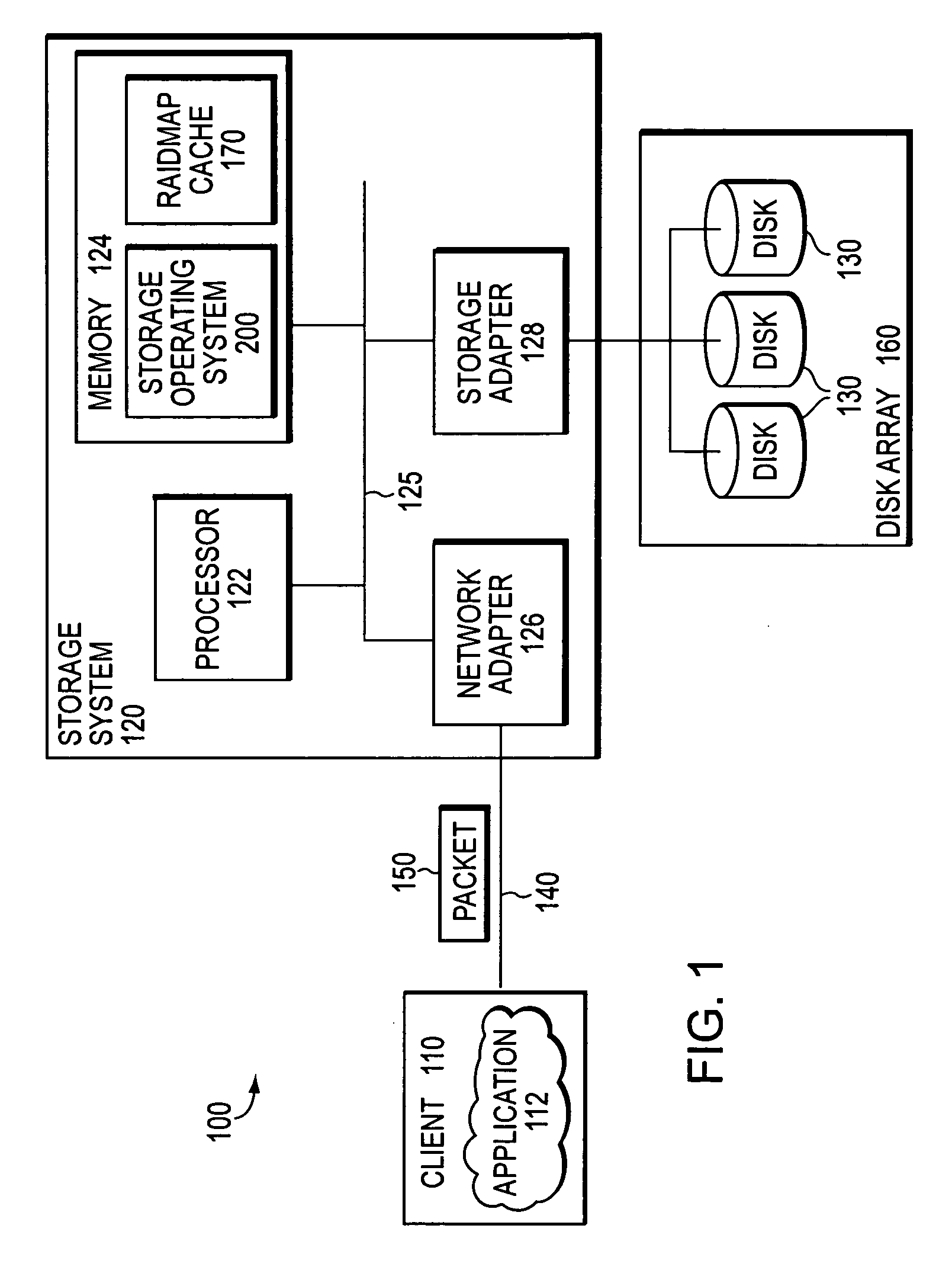
[0026]FIG. 1 is a schematic block diagram of an environment 100 including a storage system 120 that may be advantageously used with the present invention. The storage system is a computer that provides storage service relating to the organization of information on storage devices, such as disks 130 of a disk array 160. The storage system 120 comprises a processor 122, a memory 124, a network adapter 126 and a storage adapter 128 interconnected by a system bus 125. The storage system 120 also includes a storage operating system 200 that preferably implements a file system to logically organize the information as a hierarchical structure of directories, files and virtual disks (hereinafter “blocks”) on the disks.

[0027] In the illustrative embodiment, the memory 124 comprises storage locations that are addressable by the processor and adapters for storing software program code and data structures associated with the present invention. For example, a portion of the memory may be organi...


PUM


Abstract

A storage operating system is configured to assign volume block numbers (VBNs) to a volume. The system has a plurality of disks, and each disk of the plurality of disks is assigned disk block numbers (DBNs). A raidmap is configured to map the VBNs to the DBNs of the plurality of physical disks, the mapping for a particular disk stored in a disk label for the particular disk. The disk label for the particular disk is then written to the particular disk.

Description

RELATED APPLICATIONS [0001] This application is a continuation of U.S. Ser. No. 10 / 394,890 filed on Mar. 21, 2003, entitled LOCATION-INDEPENDENT RAID GROUP VIRTUAL BLOCK MANAGEMENT, by Strange et al., now issued as U.S. Pat. No. ______ on ______.FIELD OF THE INVENTION [0002] The present invention relates to storage systems and, more specifically, to a technique for mapping the capacity of storage devices into any RAID group of a storage system. BACKGROUND OF THE INVENTION [0003] A storage system typically comprises one or more storage devices into which data may be entered, and from which data may be obtained, as desired. The storage system includes a storage operating system that functionally organizes the system by, inter alia, invoking storage operations in support of a storage service implemented by the system. The storage system may be implemented in accordance with a variety of storage architectures including, but not limited to, a network-attached storage environment, a stora...

Claims


Application Information

Patent Timeline
Patent Type & Authority Applications(United States)
IPC IPC(8): G06F12/16G06F12/00
CPCG06F3/0607G06F3/0643G06F3/0647G06F3/0665H04L67/1097G06F11/1092G06F11/2056G06F2211/1023G06F3/0689
Inventor STRANGE, STEPHEN H.SCHOENTHAL, SCOTTDOUCETTE, DOUGLAS P.VISWANATHAN, SRINIVASAN
Owner NETWORK APPLIANCE INC
Why Eureka
Try Eureka