
Extracted-index addressing of byte-addressable memories

a memory and index technology, applied in the field of index addressing schemes, can solve the problems of reducing efficiency, computationally intensive encryption and decryption algorithms, etc., and achieve the effect of efficient addressing memory and loading data

Active Publication Date: 2006-11-30
ATMEL CORP
View PDF10 Cites 25 Cited by
  • Summary
  • Abstract
  • Description
  • Claims
  • Application Information

AI Technical Summary

Benefits of technology

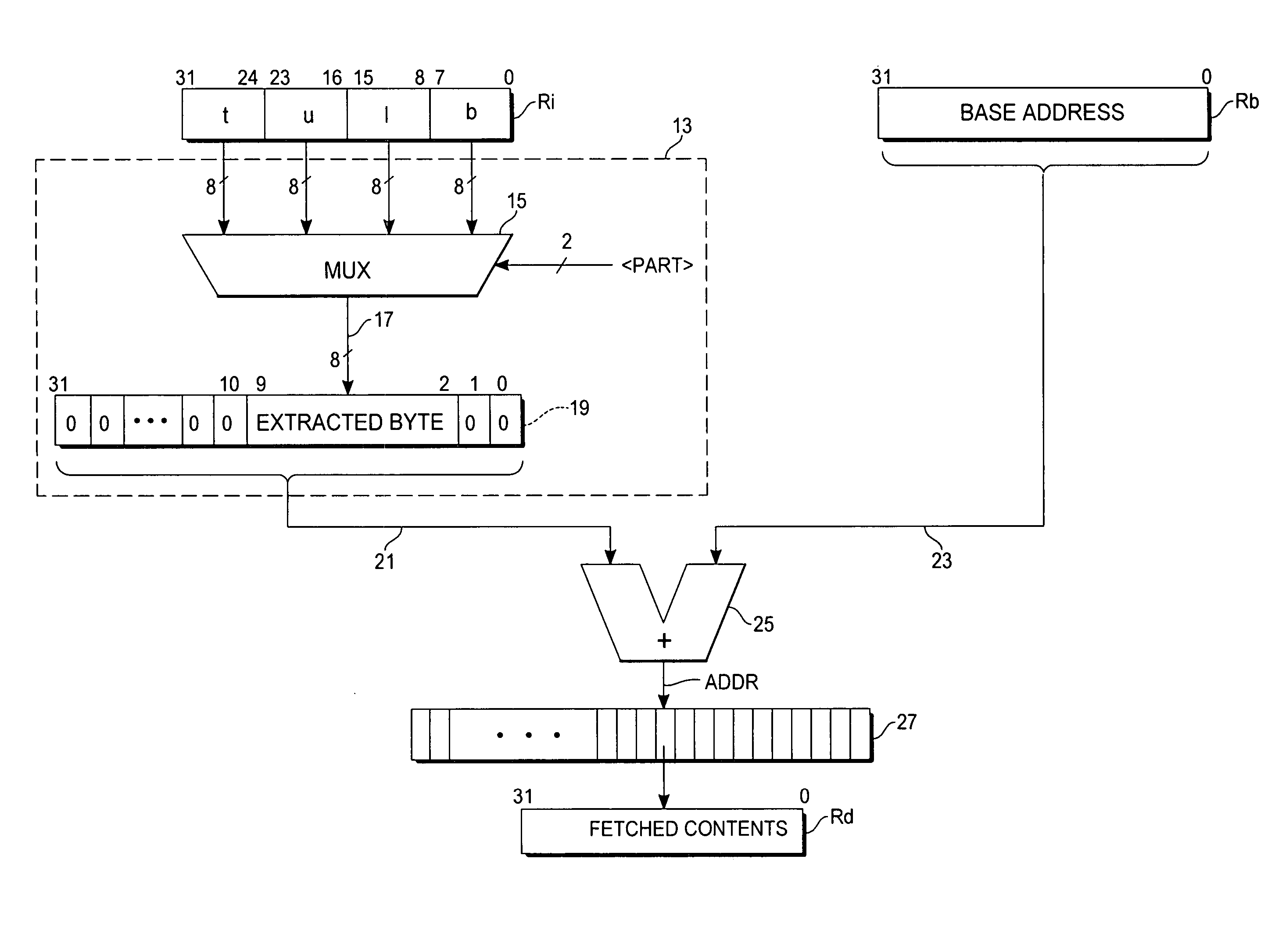
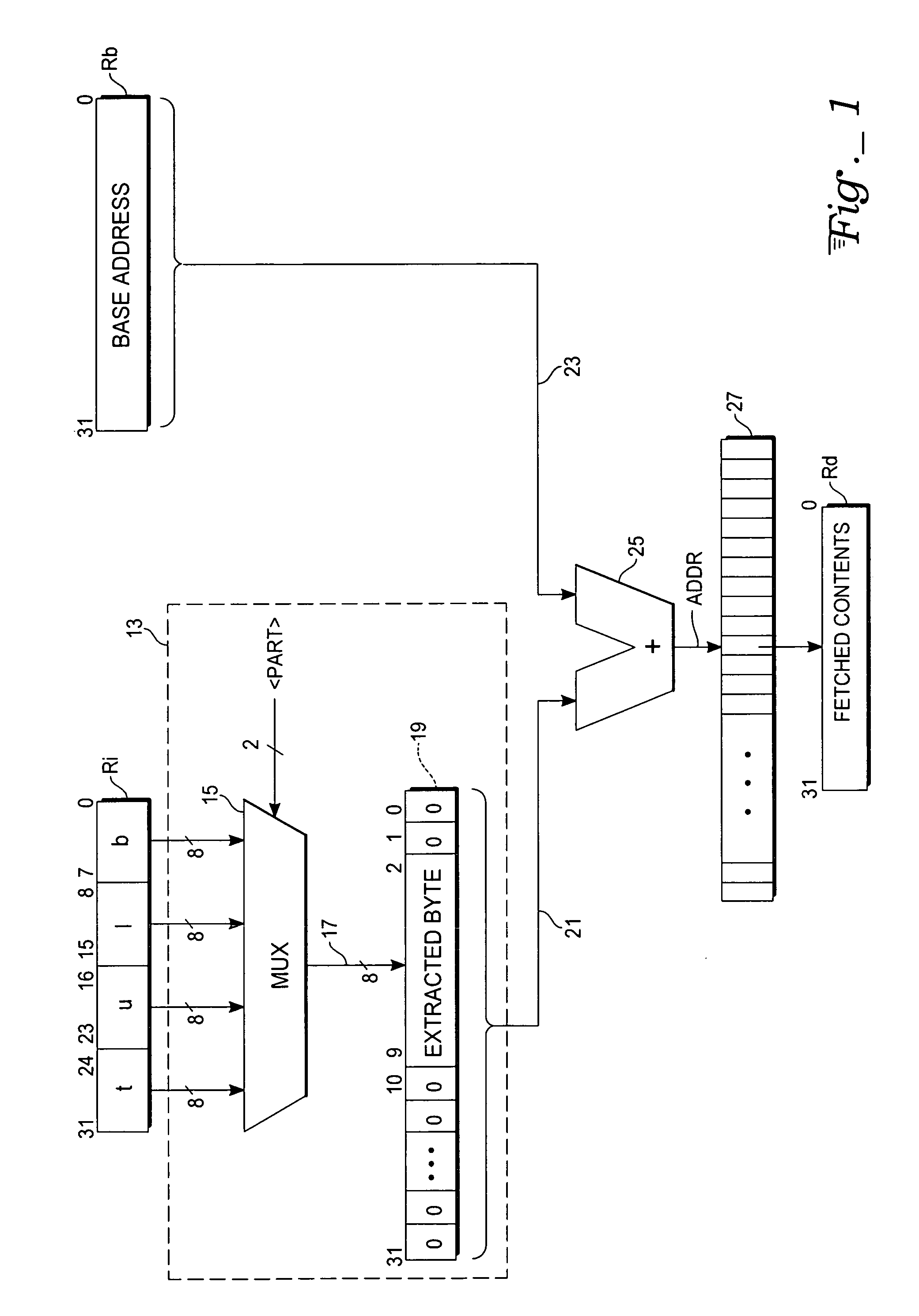
[0007] The present invention describes a microprocessor circuit responsive to an instruction for efficiently addressing memory and loading data from the resulting memory location into a register file. For example, a simple “load word with extracted index” instruction causes the circuit to extract a specified byte from an index register Ri, and to create a zero-extended word in which the extracted byte is located at bit positions [9:2], which corresponds to the effect of shifting of the extracted byte two bits to the left from its rightmost position. This combined extraction operation may be accomplished in an exemplary implementation of the circuit by using a multiplexer that is coupled to receive each of the index register's bytes, and is controlled by a byte selection value. The selected byte from the multiplexer's output is loaded directly (without any shifting operations) at the desired bit positions either into a displacement register (optional or directly into an input of an adder). The resulting word forms an offset value that is then added to the contents of a base address register Rb to form a memory address. The memory contents at that address are then fetched and loaded into a target destination register Rd. This instruction is useful, interalia, for indexing tables.

Problems solved by technology

However, where packed bytes are to be used for performing a table lookup, extracting the desired byte will normally require that a series of extra instructions be executed, which reduces efficiency.
Encryption and decryption algorithms may be quite computationally intensive.

Method used


Image

  • Extracted-index addressing of byte-addressable memories
  • Extracted-index addressing of byte-addressable memories
  • Extracted-index addressing of byte-addressable memories

Examples


Embodiment Construction

[0009] With reference to FIG. 1, each of the registers Ri, Rb, and Rd is a wordlength register (e.g., of 32 bits). Of particular interest for the present invention is the extraction of a specified byte from the index register Ri. In the exemplary embodiment shown here, the index register Ri contains four bytes, labeled as a top byte t (bits 31 to 24 inclusive), an upper byte u (bits 23 to 16 inclusive), a lower byte 1 (bits 15 to 8 inclusive) and a bottom byte b (bits 7 to 0 inclusive). The parts {t,u,l,b} of the index register Ri may be identified in an instruction using two-bit byte numbers {3,2,1,0}. Which of the hardware registers in the microprocessor are designated as the index, base and destination registers Ri, Rb, and Rd may be separately identified in an instruction using register numbers, e.g., {0,1, . . . , 15}.

[0010] An instruction may specify a byte from Ri to be extracted, zero-extended, and displaced to the left by a certain number of bits. In prior microprocessor c...


PUM


Abstract

A microprocessor circuit useful for indexed addressing of byte-addressable memories includes word-length index, base address, and destination registers designated by an instruction. The instruction also specifies one byte packed within the index register, which is to be extracted. A multiplexer has a word-wide input end accessing all of the bytes of the index register, and responsive to byte selection control passes the specified byte to its output. The extracted byte is provided directly at specific bit positions of a zero-extended address offset word. The offset word is added to the base address, the sum being used to address memory contents that are loaded into the destination register.

Description

TECHNICAL FIELD [0001] The invention relates generally to memory accesses in microprocessor architectures, including both load-store (RISC machine) architectures and memory-oriented (CISC machine) architectures. The invention relates more particularly to those index addressing schemes that permit a microprocessor to access memory structures, especially byte-addressable memories, more efficiently. BACKGROUND ART [0002] Operations involving two operands, where one of the operands is a byte value and the other operand is a known constant value are often feasible to compute with a look-up table, since there are only 256 (=28) possible byte values and corresponding outcomes, so the look-up table will be rather small. For computationally intensive operations (e.g., division, exponentiation), accessing look-up tables tend to be much faster than full hardware or software execution of the same operation. If the processor architecture supports memory loads with register-indexed offsets, the l...

Claims


Application Information

Patent Timeline
IPC IPC(8): G06F9/34
CPCG06F9/30018G06F9/355G06F9/30032G06F9/30036G06F13/00
Inventor PEDERSEN, RONNYRENNO, ERIK K.STROM, OYVIND
Owner ATMEL CORP
Learn More