
Flexible imaging pressure sensor

Active Publication Date: 2006-12-07
LENOVO PC INT
View PDF18 Cites 93 Cited by
  • Summary
  • Abstract
  • Description
  • Claims
  • Application Information

AI Technical Summary

Benefits of technology

[0007] The present invention provides a sensor for a textured surface (e.g., a fingerprint). The sensor includes a flexible substrate and a flexible membrane supported above the substrate by one or more spacers. The sensor also includes multiple pressure sensor elements responsive to a separation between parts of the membrane and corresponding parts of the substrate. The membrane is conformable to the textured surface being sensed, so the variation in separation between substrate and membrane is representative of the textured surface being sensed. A preferred sensor array arrangement has a set of parallel substrate electrodes on the substrate facing the membrane and a set of parallel membrane electrodes on the membrane facing the substrate, where the substrate and membrane electrodes are perpendicular to each other. The sensor array is preferably an entirely passive structure including no active electrical devices, to reduce cost. Row and column addressing circuitry can be provided as separate units (e.g., ASIC chips) to be hybrid integrated with the sensor array.
[0008] The present invention provides several significant advantages. The flexibility of the substrate permits sensors according to the invention to be used in applications where rigid sensors would break, such as credit card and identity card applications. The flexible substrate also permits high-volume fabrication methods (e.g., roll-level processing), to reduce cost. In preferred embodiments where the substrate and membrane define a switch array, the sensor output is advantageously an inherently binary signal corresponding to whether or not the relevant switch is open or closed. Here a switch is regarded as any structure having an electrical resistance responsive to a mechanical input (e.g., having movable electrical contacts, including a pressure sensitive resistor, etc.).

Problems solved by technology

In practice, implementation of such sensor approaches is often excessively costly.
Such large chips are costly to fabricate, since the number of chips per semiconductor wafer is relatively low.
Furthermore, sensors having rigid and breakable substrates (e.g., conventional silicon substrates) cannot be used for applications such as smart credit / identity cards where the sensor must survive a certain degree of flexure.
In addition, the polymeric transistors used in such works can be unreliable in commonly encountered environmental conditions such as high humidity (which causes polymer transistor degradation).
Furthermore, the fabrication of more traditional transistors, such as thin film transistors, requires exposure of the substrate to high temperatures during processing, which can cause degradation of typical polymer based flexible substrates.
A disadvantage of this approach is that the strain gauge output is analog.
It is often preferred for fingerprint sensors to provide inherently digital outputs, since a digital image is often required in practice and post-conversion of an analog sensor image to a binary image is frequently error-prone.

Method used


Image

  • Flexible imaging pressure sensor
  • Flexible imaging pressure sensor
  • Flexible imaging pressure sensor

Examples


Embodiment Construction

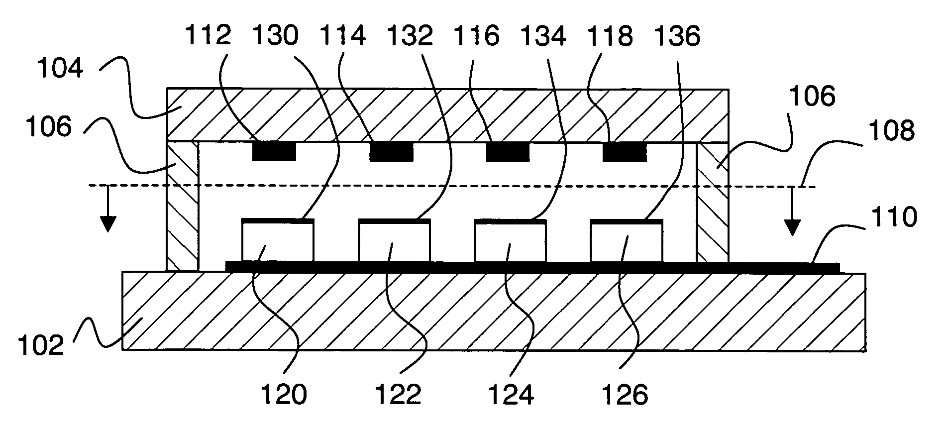
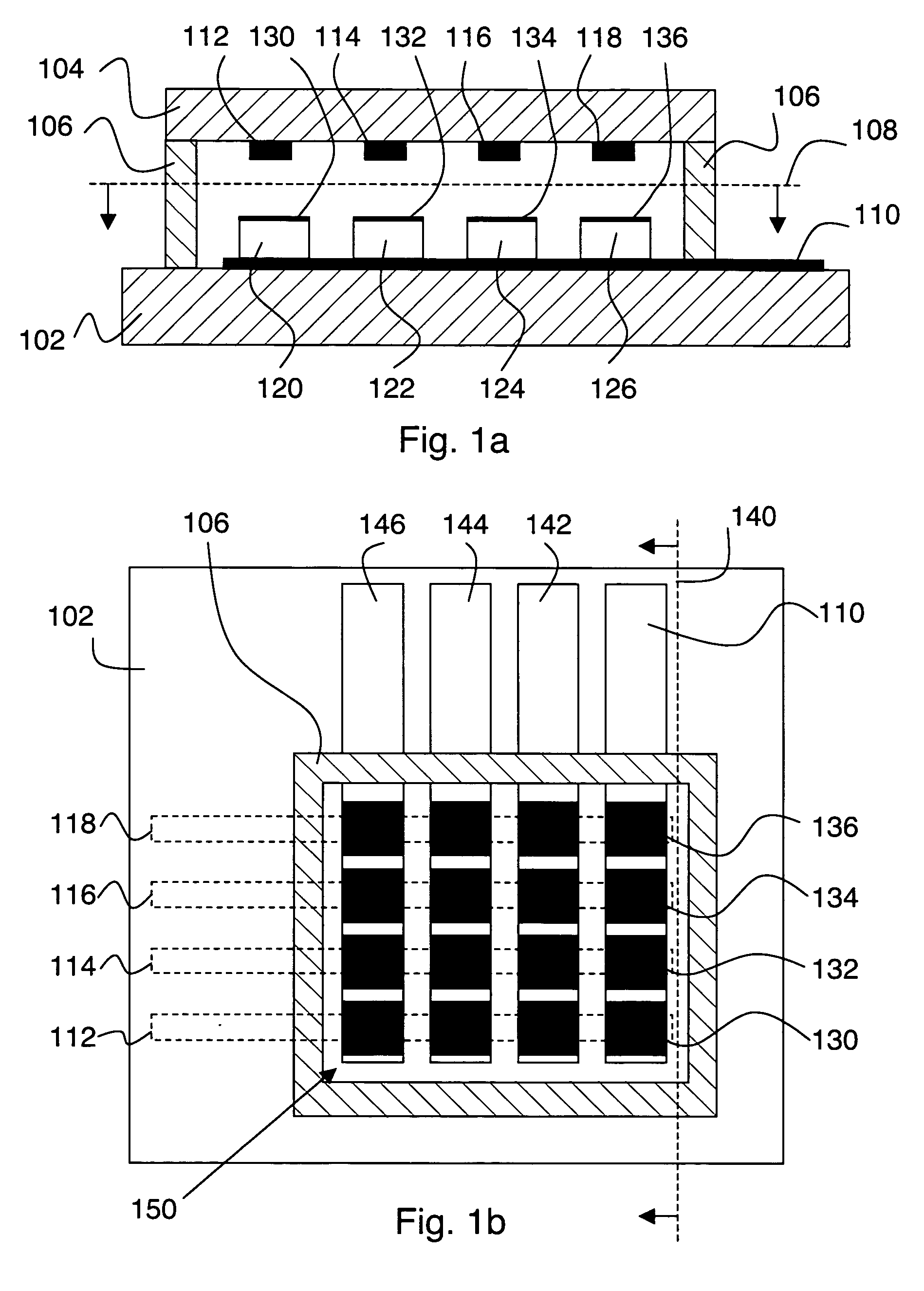
[0017]FIGS. 1a-b show cutaway side and top views, respectively, of an embodiment of the invention. More specifically, FIG. 1a shows a cutaway view along line 140 on FIG. 1b, and FIG. 1b shows a cutaway view along line 108 on FIG. 1a. A flexible substrate 102 and a flexible membrane 104 are connected to a spacer 106. Membrane 104 is conformable to a textured surface to be sensed (e.g., a fingerprint). A plurality of pressure sensor elements 150 is included, each pressure sensor element being responsive to a separation between part of the membrane and a corresponding part of the substrate. Spacer 106 determines, in part, a nominal separation between membrane 104 and substrate 102 for each pressure sensor element. Here the nominal separation is the separation between membrane and substrate when no textured surface is making contact with the top surface of membrane 104. As used herein, “flexible” is taken to refer to materials or structures having a Young's modulus of less than 25 GPa. ...


PUM


Abstract

A sensor for a textured surface (e.g., a fingerprint) is provided. The sensor includes a flexible substrate and a flexible membrane supported above the substrate by one or more spacers. The sensor also includes multiple pressure sensor elements responsive to a separation between parts of the membrane and corresponding parts of the substrate. The membrane is conformable to the textured surface being sensed, so the variation in separation between substrate and membrane is representative of the textured surface being sensed. A preferred sensor array arrangement has a set of parallel substrate electrodes on the substrate facing the membrane and a set of parallel membrane electrodes on the membrane facing the substrate, where the substrate and membrane electrodes are perpendicular. The sensor array is preferably an entirely passive structure including no active electrical devices, to reduce cost. Row and column addressing circuitry can be provided as separate units (e.g., ASIC chips) to be hybrid integrated with the sensor array.

Description

FIELD OF THE INVENTION [0001] This invention relates to pressure sensors for providing a tactile image of a textured surface, such as a fingerprint. BACKGROUND [0002] Security and identification often relies on fingerprint data. Accordingly, sensors for providing fingerprint images have been under development for some time. Many such sensors employ an array of sensor pixels making direct contact with a finger. Readout of the sensor pixels provides fingerprint image data. Known approaches for providing such sensor pixels include capacitive sensing (e.g., as in U.S. Pat. No. 6,694,269), and temperature or pressure sensing (e.g., as in U.S. Pat. No. 4,429,413). Further references relating to pressure sensing include: U.S. Pat. No. 5,844,287, U.S. Pat. No. 6,672,174, U.S. Pat. No. 6,578,436, and US 2002 / 0121145. [0003] In many cases, sensors based on pressure sensing include a flexible membrane that conforms to the valleys and ridges of an applied fingerprint. The membrane is typically ...

Claims


Application Information

Patent Timeline
IPC IPC(8): G01D7/00
CPCG01L1/142G06K9/0002G01L1/205G06V40/1306
Inventor GANAPATHI, SRINIVASAN K.DECONDE, KEITH T.GLUCK, RANDOLPH S.
Owner LENOVO PC INT
Features
  • Generate Ideas
  • Intellectual Property
  • Life Sciences
  • Materials
  • Tech Scout
  • Unparalleled Data Quality
  • Higher Quality Content
  • 60% Fewer Hallucinations
Learn More