Hands are some of the most commonly operated upon extremities because they are required to complete many tasks and activities and are thus highly at risk to injury.
Additionally, microsurgical techniques are generally required because the tissues that make the functions of the hand possible are small by nature.
Current techniques for performing
hand surgery in the emergency room and elsewhere are inefficient and frustrating.
Maintaining the hand in a desired position can be a difficult task when qualified assistants are not readily available, which is often the case during late-night, weekend, or very busy emergency room situations.
Additionally, gathering the necessary supplies from various areas in the emergency room prior to operation can be a burdensome task.
Due to a lack of centralized storage, the surgeon may find himself or herself walking back and forth between the patient and various areas of the room to gather surgical tools, sutures, needles, gauze, and other items required to complete the
surgery.
The surgeon may experience additional
frustration if supply amounts have not been maintained or if items have changed locations.
The
clutter typically increases throughout the operation as surgeon uses different tools and instruments and places them back on the table.
Any increased
operating time resulting from the lack of instrument management increases the overall cost of the
surgery and can compromise the quality of the operation.
Additionally, the lack of instrument management increases the potential of accidental injury from exposed scalpel blades and the like.
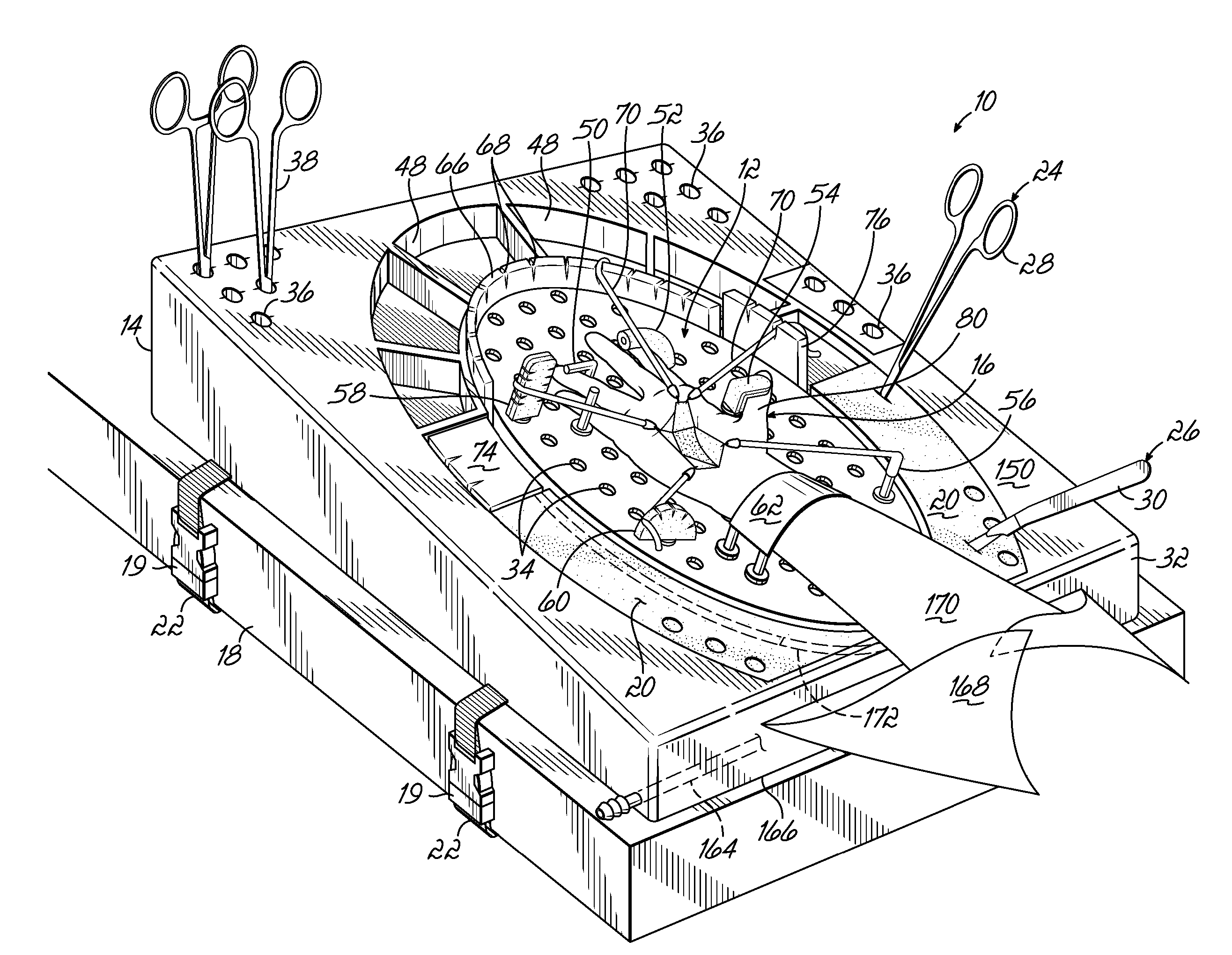
Use of the tools themselves can also be a challenging task.
In particular, areas of tissue on the hand typically obstruct access to the
surgical site being operated upon.
Because assistants are not always available to hold the stays during an operation, many surgeons place some sort of
retractor frame around the surgical site.
The ability to use a stay to retract tissue in a desired three-dimensional direction is limited by the spacing of the notches and their position relative to the tissue.
Such a technique, however, may not sufficiently capture the fluids due to splashing while the fluids are being applied.
Moreover, the bin or basin may not be large enough to cover the entire area where drainage is likely to occur and can create a mess when attempting to dispose of its contents.
As a result, the surgeon has a more difficult time maintaining a sterile surgical site and reducing his or her own
exposure to potentially contaminated and biohazardous fluids.
Although several attempts have been made to facilitate surgical operations on a patient's extremities, these attempts merely focus on one or few of the challenges associated with the operations and do not adequately ease the burden on surgeons.
Despite the improvements in stability, however, such devices do not adequately address the challenges associated with tissue retraction, instrument management, and
fluid management.
In particular, although most of the tables provide some means for securing a hand or the like during surgery, the tables still limit the manner by which surgical stays may be used to retract tissue.
This row of notches, or “Scott fencing,” suffers from the same drawbacks as the notched framing discussed above—the desired direction of retraction is limited by the spacing of the notches and their position in 3 dimensions relative to the tissue.

