PLL controller applying a multiplier coefficient appropriate for a phase error, and a method therefor

a phase error and multiplier coefficient technology, applied in the field of phaselocked loop controllers, can solve the problems of not being standardized and providing jittered video images, and achieve the effects of reducing jitter, reducing tracking rate, and avoiding drawbacks

Active Publication Date: 2006-12-07
LAPIS SEMICON CO LTD
View PDF1 Cites 6 Cited by
  • Summary
  • Abstract
  • Description
  • Claims
  • Application Information

AI Technical Summary

Benefits of technology

[0019] The PLL controller also can eliminate a drawback such that, when a video signal is a weak electric field signal and an error caused by the false detection of a sync signal is large, tracking rate would become faster and jitter occurs frequently.

Problems solved by technology

Conventionally, in devices such as digital video decoders, a frequency error has occurred between an input video signals and the reference signal, thus providing a jittered video image.
However, some kinds of video signals are not standardized but include a line whose period is deviated from the standardized period, i.e. not consistent with the reference period.

Method used


Image

  • PLL controller applying a multiplier coefficient appropriate for a phase error, and a method therefor
  • PLL controller applying a multiplier coefficient appropriate for a phase error, and a method therefor
  • PLL controller applying a multiplier coefficient appropriate for a phase error, and a method therefor

Examples


Embodiment Construction

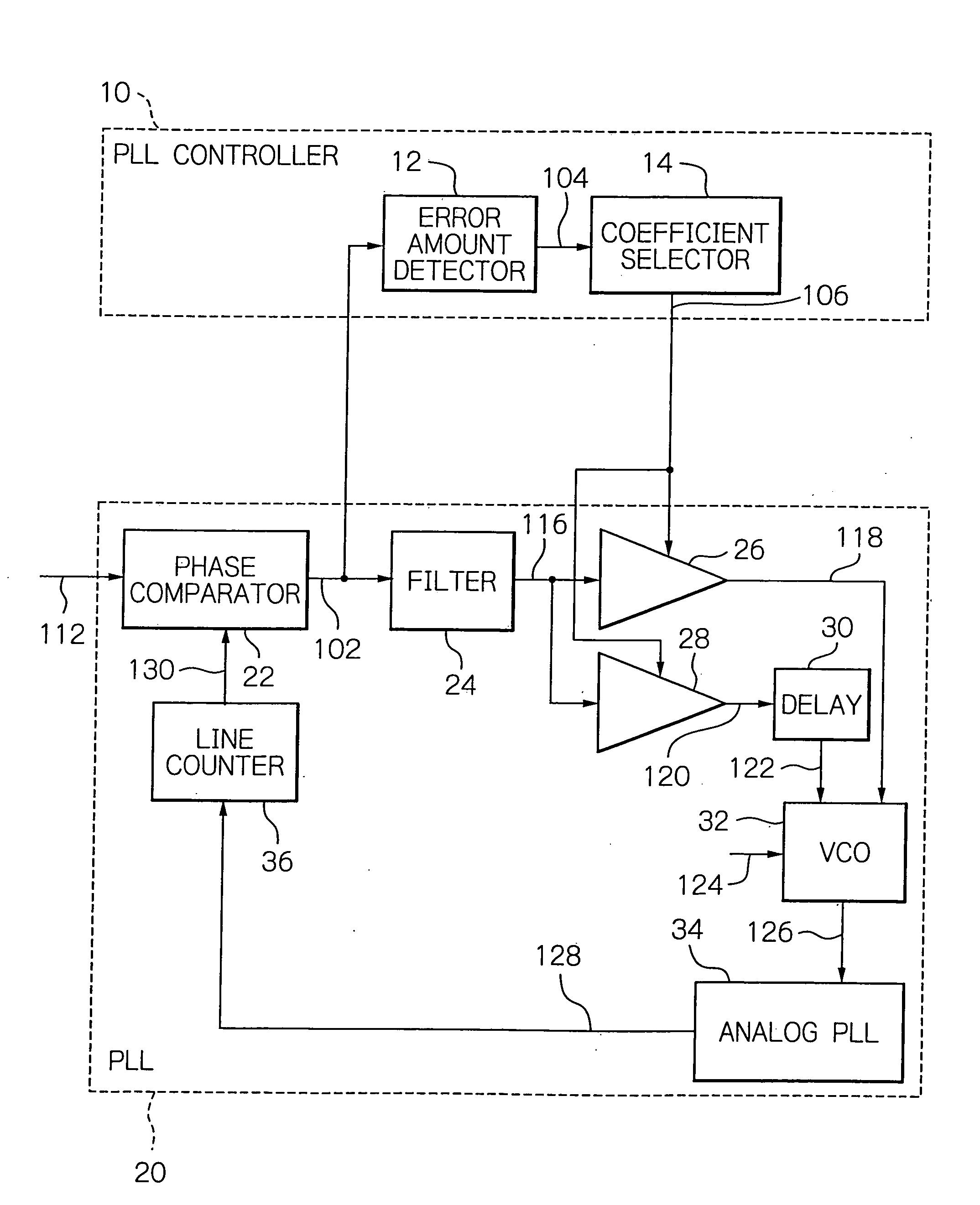
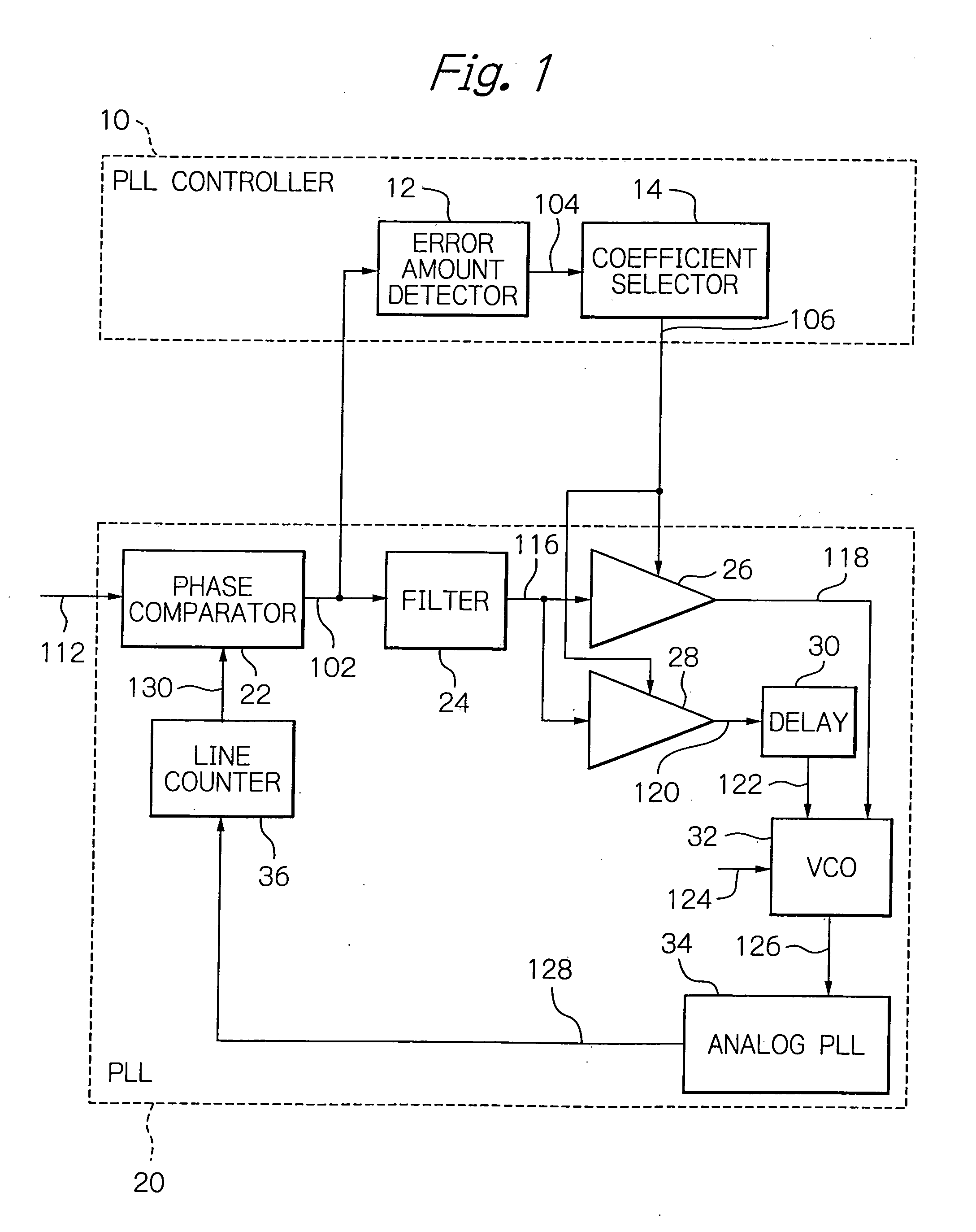
[0028] With reference to the accompanying drawings, a phase-locked loop (PLL) controller according to a preferred embodiment of the present invention will now be described in detail. As shown in FIG. 1, a PLL controller 10 of the present invention is adapted to detect a coefficient signal 106 by an error amount detector 12 and a coefficient selector 14 on the basis of a phase error 102 provided by a phase comparator 22 of a phase-locked loop, and to use the coefficient signal 106 to thereby control the tracking rate of the phase-locked loop 20. Parts not directly related for understanding the invention are omitted from the drawings and description so as to avoid redundancy.

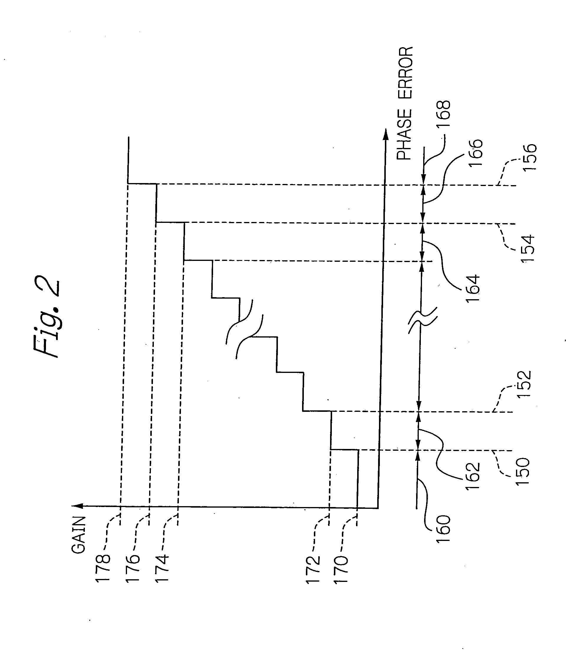
[0029] The error amount detector 12 in the preferred embodiment functions as controlling the coefficient selector 14 according to the inputting phase error 102. Specifically, the error amount detector 12 uses one or more thresholds such as N thresholds, where N is a predetermined positive integer, and measures th...


PUM


Abstract

A PLL controller for controlling the tracking rate of a phase-locked loop (PLL), in particular, controlling coefficients to be input to a device such as a multiplier of the phase-locked loop. A PLL controller receives a phase error between a horizontal sync signal in a video signal and a reference signal. Then an error amount detector measures the phase error using the N thresholds to output a control signal indicating any of N+1 levels. A coefficient selector outputs one of the N+1 gains as a coefficient signal, the one gain corresponding to the level indicated by the control signal, so that the tracking rate of the phase-locked loop is controlled in response to the input video signal, and thus a high-quality video image with less jitter can be provided.

Description

BACKGROUND OF THE INVENTION [0001] 1. Field of the Invention [0002] The present invention relates to a phase-locked loop (PLL) controller for controlling a phase-locked loop provided for, e.g. a digital video decoder for decoding video signals, and, in particular, a PLL controller for controlling a coefficient to be input to a device such as an analog multiplier in the phase-locked loop. The present invention also relates to a method for controlling the same. [0003] 2. Description of the Background Art [0004] Conventionally, in devices such as digital video decoders, a frequency error has occurred between an input video signals and the reference signal, thus providing a jittered video image. [0005] For example, as shown in FIG. 5, a video signal 400 generally has sets of vertical blanking period 402 and effective video period 404. In each of the sets, the period of a field is defined starting with a vertical sync pulse 406 in the vertical blanking period 402. Furthermore, as shown i...

Claims


Application Information

Patent Timeline
Patent Type & Authority Applications(United States)
IPC IPC(8): H04N5/04H03L7/093H04N5/12
CPCH04N5/12H04N5/04
Inventor SATOH, YASUNORIAKIYAMA, TAKAAKI
Owner LAPIS SEMICON CO LTD
Why Eureka
Try Eureka