
Method of manufacturing semiconductor device

a manufacturing method and semiconductor technology, applied in semiconductor devices, semiconductor/solid-state device details, electrical devices, etc., can solve the problem of increasing the thickness of the lower metal layer b>16/b>, and achieve the effect of improving yield and minimizing the variation of the contact resistance between the upper metal layer and the lower metal layer

Active Publication Date: 2006-12-07
MOSAID TECH
View PDF3 Cites 9 Cited by
  • Summary
  • Abstract
  • Description
  • Claims
  • Application Information

AI Technical Summary

Benefits of technology

[0007] An embodiment of the present invention relates to a method of manufacturing a semiconductor device in which variations in the contact resistance between the upper metal layer and the lower metal layer can be minimized and yields can be improved when the semiconductor device is mass produced.

Problems solved by technology

In the case of highly-integrated semiconductor devices, however, there is a limit to how thick the lower metal layer 16 can be increased.

Method used


Image

  • Method of manufacturing semiconductor device
  • Method of manufacturing semiconductor device
  • Method of manufacturing semiconductor device

Examples


Embodiment Construction

[0016] In the following detailed description, only certain specific embodiments of the present invention have been shown and described by way of illustration. As those skilled in the art will realize, the described embodiments may be modified in various ways, all without departing from the spirit or scope of the present invention. Accordingly, the drawings and description are to be regarded as illustrative in nature and not restrictive. Like reference numerals designate like elements throughout.

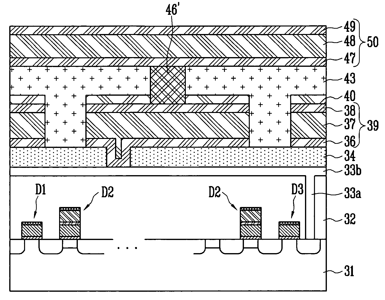
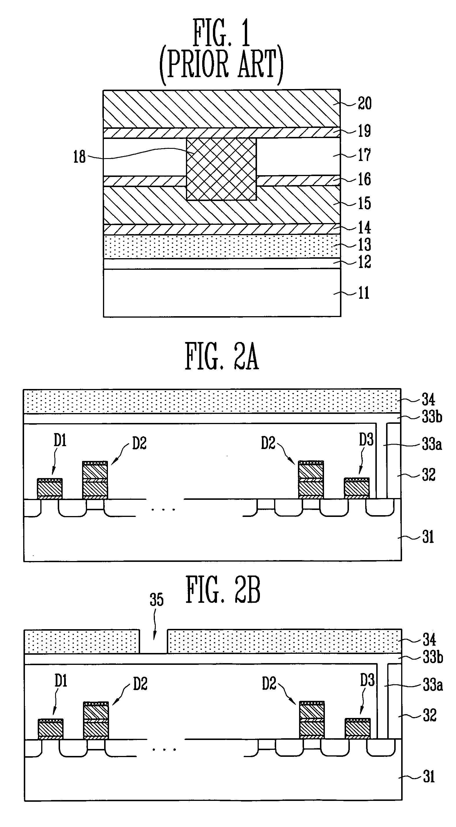
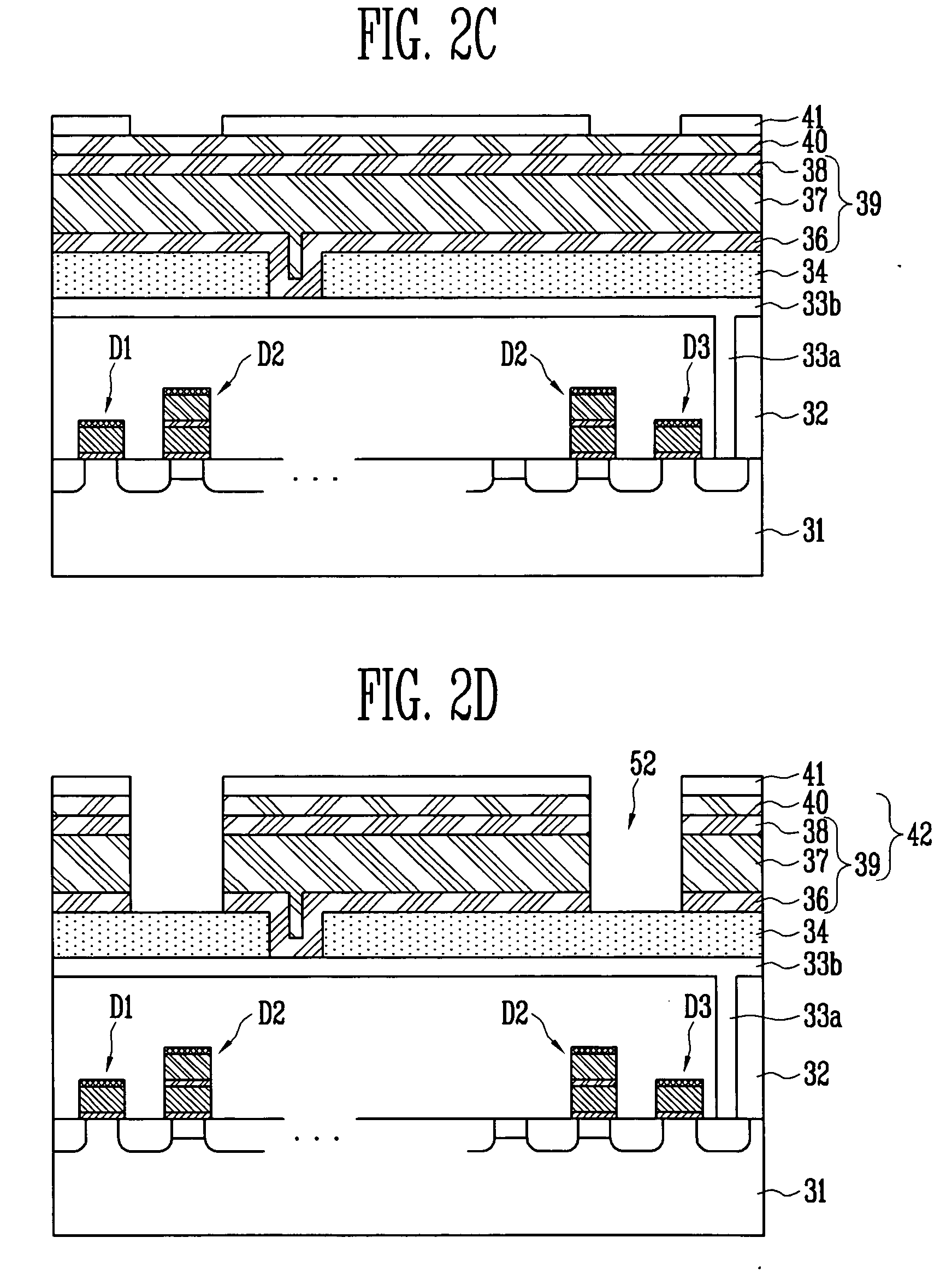
[0017] Referring to FIG. 2A, a semiconductor substrate 31 is provided on which a plurality of unit elements D1, D2 and D3 are formed. D1 designates a source select transistor, D2 designates a memory cell transistor and D3 designates a drain select transistor. These unit elements may also be referred to as gates or gate structures. An interlayer insulation film 32 is then formed on the entire structure. After that a photolithography and etch process is performed on the interlayer insulation f...


PUM


Abstract

A method of manufacturing a semiconductor device includes providing a semiconductor substrate on which a plurality of transistors are defined; forming a wiring pattern over the transistors, the wiring pattern contacting at least one transistor; depositing a first oxide film over the wiring pattern; defining a first contact hole on the oxide film, the first contacting hole exposing the wiring pattern; forming a lower metal layer having a first barrier metal layer, a first metal layer and a second barrier metal layer over the oxide film, the lower metal layer filling the first contact hole; forming a contact hole stop conduction layer over the lower metal layer; depositing a second oxide film over the contact hole stop conduction layer; etching a selected portion of the second oxide film to form a hole exposing the contact hole stop conduction layer; etching the exposed contact hole stop layer to define a second contact hole; forming a contact plug within the second contact hole, the contact plug contacting the lower metal layer; and forming an upper metal layer including a third barrier metal layer and a second metal layer, the upper metal layer contacting the contact plug.

Description

BACKGROUND [0001] The present invention relates to a method of manufacturing a semiconductor device. More particularly, the present invention relates to a method of manufacturing a semiconductor device including a multi-layer metal wiring pattern. [0002] Generally, a semiconductor device includes a device pattern layer 12 having a plurality of unit device patterns (not shown) on a semiconductor substrate 11, as shown in FIG. 1. An Inter Layer Dielectric (ILD) oxide film 13 is deposited on the device pattern layer 12. Lower metal layers 14, 15 and 16 are sequentially formed on the ILD oxide film 13. The lower metal layers 14, 15 and 16 are patterned. [0003] An Inter Metal Dielectric (IMD) oxide film 17 is then deposited on the entire structure. A contact hole (not shown) for forming a contact plug 18 is formed within the IMD oxide film 17. Thereafter, the contact hole is filled with a conductive material to form the contact plug 18. Upper metal layers 19, 20 are sequentially formed o...

Claims


Application Information

Patent Timeline
Patent Type & Authority Applications(United States)
IPC IPC(8): H01L21/4763
CPCH01L21/76802H01L21/76805H01L2924/0002H01L21/76844H01L21/7685H01L21/76865H01L21/76885H01L23/5222H01L23/5226H01L23/53223H01L23/53238H01L23/5329H01L23/53295H01L2924/00H01L21/28
Inventor PARK, SHIN SEUNG
Owner MOSAID TECH
Learn More