Power series type predistorter for multi-frequency bands operation

a power series type, multi-frequency band technology, applied in the direction of digital transmission, amplifier modification to reduce non-linear distortion, baseband system details, etc., can solve the problem of disadvantageous power series type predistorter adapted for each frequency band, and achieve the effect of simplifying and reducing the size of the device, reducing power consumption, and reducing the components of distortion

Inactive Publication Date: 2006-12-07
NTT DOCOMO INC
View PDF11 Cites 57 Cited by
  • Summary
  • Abstract
  • Description
  • Claims
  • Application Information

AI Technical Summary

Benefits of technology

[0028] The power series type predistorter for multi-frequency bands according to the present invention divides a plurality of band signals into respective bands, causes the odd order distortion to be generated for each frequency band, adjusts each frequency band so as to reduce the distortion components generated by said distortion components at a power amplifier, and combines the distortion components with the transmitting signals and inputs the result in the power amplifier. As a result, odd order distortion components in each frequency band at the output side of the power amplifier are removed.
[0029] That is to say, the predistorter can adjust the quantity of distortion compensation independently for each frequency band and collectively process the quantity of distortion compensation of a plurality of frequency bands. Accordingly, the present invention can simplify and downsize the device, and reduce power consumption.
[0030] The amplifier configuration of the present invention is characterized in that i

Problems solved by technology

A power series type predistorter adapted for each frequency band is more disadvantageous than

Method used


Image

  • Power series type predistorter for multi-frequency bands operation
  • Power series type predistorter for multi-frequency bands operation
  • Power series type predistorter for multi-frequency bands operation

Examples


first embodiment

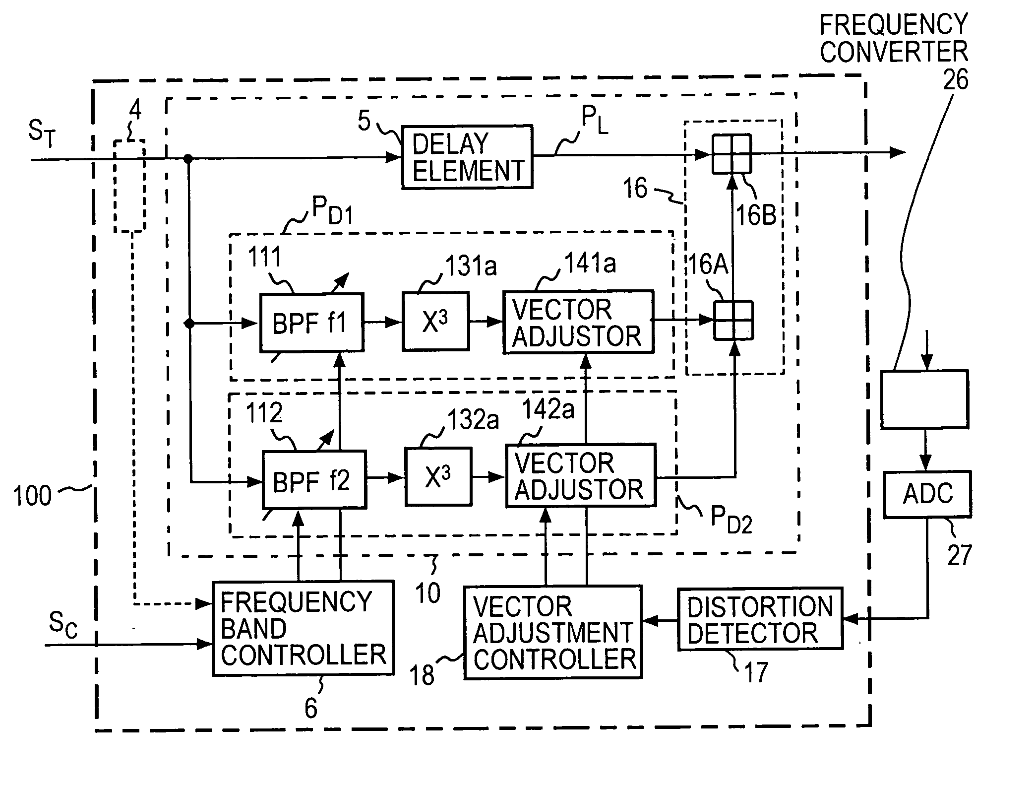
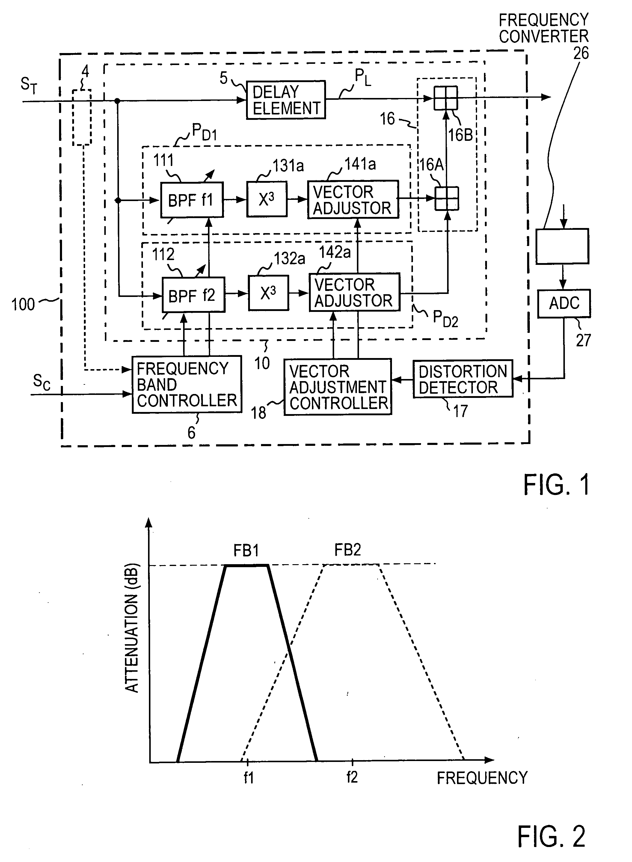
[0052]FIG. 1 shows the first embodiment of a fundamental configuration of a power series type predistorter for multi-frequency bands according to the present invention. An input transmitting signal ST may be a base band signal, an intermediate frequency signal or a wireless frequency signal. The predistorter 100 includes a predistortion circuit 10, a frequency band controller 6, a distortion detector 17, and a vector adjustment controller 18. The predistortion circuit 10 includes a linear transmission path PL, a third order distortion generating path PD1 for a first frequency band, a third order distortion generating path PD2 for a second frequency band, and a combiner 16 for combining outputted signals from these paths. The predistorter shown in FIG. 1 realizes distortion compensation in dual frequency bands (represented by the center frequencies f1 and f2). If the dual frequency bands are applied to a mobile radio, f1 is for 800 MHz band, for example, and f2 is for 1.5 GHz band, f...

second embodiment

[0068]FIG. 8 shows a second embodiment of the predistorter according to the present invention. This embodiment shows a case where the predistorter 100 consists of an analog circuit and input intermediate frequency signals ST1 and ST2 whose center frequencies are f1 and f2 are inputted from transmitters 41 and 42. The center frequencies f1 and f2 of the transmitting signals ST1 and ST2 are assumed to be divided by about 100 MHz apart from each other, which is large enough than the bandwidth of each band. In this embodiment, the distortion generating paths PD1 and PD2 of the frequency bands f1 and f2 are each adapted to generate a third order distortion and a fifth order distortion of the input signals so as to compensate for the third order distortion and the fifth order distortion.

[0069] A divider 8 for an input of an analog predistortion circuit 10 is constructed of a wide band (equal to or greater than the bandwidth of an input signal) directional coupler or a power divider. The ...

third embodiment

[0075]FIG. 9 shows a third embodiment of the predistorter according to the present invention. The embodiment is adapted to realize the predistorter 100 shown in FIG. 8 by digital signal processing, with each signal consisting of a pair of an in-phase signal (I signal) and a quadrature signal (Q signal). Also in this embodiment, the predistortion circuit 10 has a divider 8 for dividing input signals, a linear transmission path PL consisting of a delay memory as the delay element 5, a variable band signal extractor 111 for extracting signals in the frequency band FB1 by digital signal processing, a variable band signal extractor 112 for extracting signals in the frequency band FB2 by digital signal processing, third and fifth order distortion generators 131a, 131b and 132a, 132b for generating a third order distortion component and a fifth order distortion component in each of the frequency bands FB1 and FB2, and vector adjustors 141a, 141b, 142a and 12b.

[0076] Each of the combiners ...


PUM


Abstract

A power series type predistorter for multi-frequency bands includes a linear transmission path PL provided with a delay element 5 and distortion generating paths PD1 and PD2 for a plurality of frequency bands in parallel; wherein each of the distortion generating paths PD1 and PD2 for a plurality of frequency bands includes variable band signal extractors 111 and 112 for extracting a signal in each frequency band from input signals and distortion generators 131a and 132a which is provided with the extracted signals and which generates at least one of the odd number distortion components of the signals and making it as an output from the distortion generating paths PD1 and PD2 for frequency bands; and wherein the frequency band controller 6 controls frequency bands of the variable band signal extractors 111 and 112.

Description

TECHNICAL FIELD [0001] The present invention relates to a power series type predistorter for multi-frequency bands operation, for compensating a distortion generated by a power amplifier that amplifies the power of a high frequency signal adaptively changing a plurality of frequency bands. BACKGROUND ART [0002] A predistortion linearizer employing digital signal processing (hereinafter referred to as a digital predistortion method) has been known as one of non-linear distortion compensation methods of a microwave power amplifier (for example, Patent literature 1). The digital predistortion method is characterized by eliminating a complicate analog circuit by enabling a predistorter to be configured with digital signal processing. [0003] As a configuration of a digital predistorter, a configuration with a lookup table having a table for previously linearizing non-linear characteristics of an amplifier has been known (for example, Non Patent literature 1 and Patent literature 2). The ...

Claims


Application Information

Patent Timeline
IPC IPC(8): H04B1/04
CPCH03F2200/111H03F1/3258H03F1/32
Inventor SUZUKI, YASUNORINARAHASHI, SHOICHI
Owner NTT DOCOMO INC
Why Eureka
Try Eureka