Nasal valve treatment method & apparatus

a treatment method and a technology for a nasal valve, applied in the field of nasal valve collapse treatment methods and equipment, can solve the problems of affecting the safety of patients, so as to achieve the effect of maintaining material strength

Active Publication Date: 2006-12-07
MEDTRONIC XOMED INC
View PDF30 Cites 104 Cited by
  • Summary
  • Abstract
  • Description
  • Claims
  • Application Information

AI Technical Summary

Benefits of technology

[0010] According to a preferred embodiment of the present invention, the method and apparatus are disclosed for treating a nasal valve condition. The method includes surgically forming an access path to create a pocket on a side of the patient's nose. The pocket is positioned between a soft tissue layer (external skin or nasal mucosa) and opposing surfaces of upper and lower cartilages of the nose. The pocket spans a junction between the upper and lower cartilages. An implant is selected having a length, width and thickness sized to reside within the pocket. The length is sized to span the junction. The width is sized to be less than the width of the upper and lower cartilages. The thickness of the implant is as thin as possible while maintaining material strength to resist bending in response to inhalation pressures at the nasal valve. The implant is placed through the access path into the pocket with the length oriented spanning the junction. A delivery system for placement of the implant includes a surgical tool for forming the access path and for delivering the implant into the access path.

Problems solved by technology

The nasal valve disrupts the laminar flow characteristics of air, which would otherwise insulate the airflow from the mucosa of the nose.
While the airflow restriction of the nasal valve is an important function, a weakened or otherwise compromised nasal valve can obstruct the nasal passage.
Also, such compromise can result from prior nasal surgery which commonly include cosmetic surgeries.
However, such devices can be uncomfortable and may require the patient to remove and replace the device on a periodic basis.

Method used


Image

  • Nasal valve treatment method & apparatus
  • Nasal valve treatment method & apparatus
  • Nasal valve treatment method & apparatus

Examples


Embodiment Construction

[0034] With reference now the various drawing figures in which identical elements are numbered identically throughout, a description of the preferred embodiment of the present invention will now be provided.

A. Anatomy

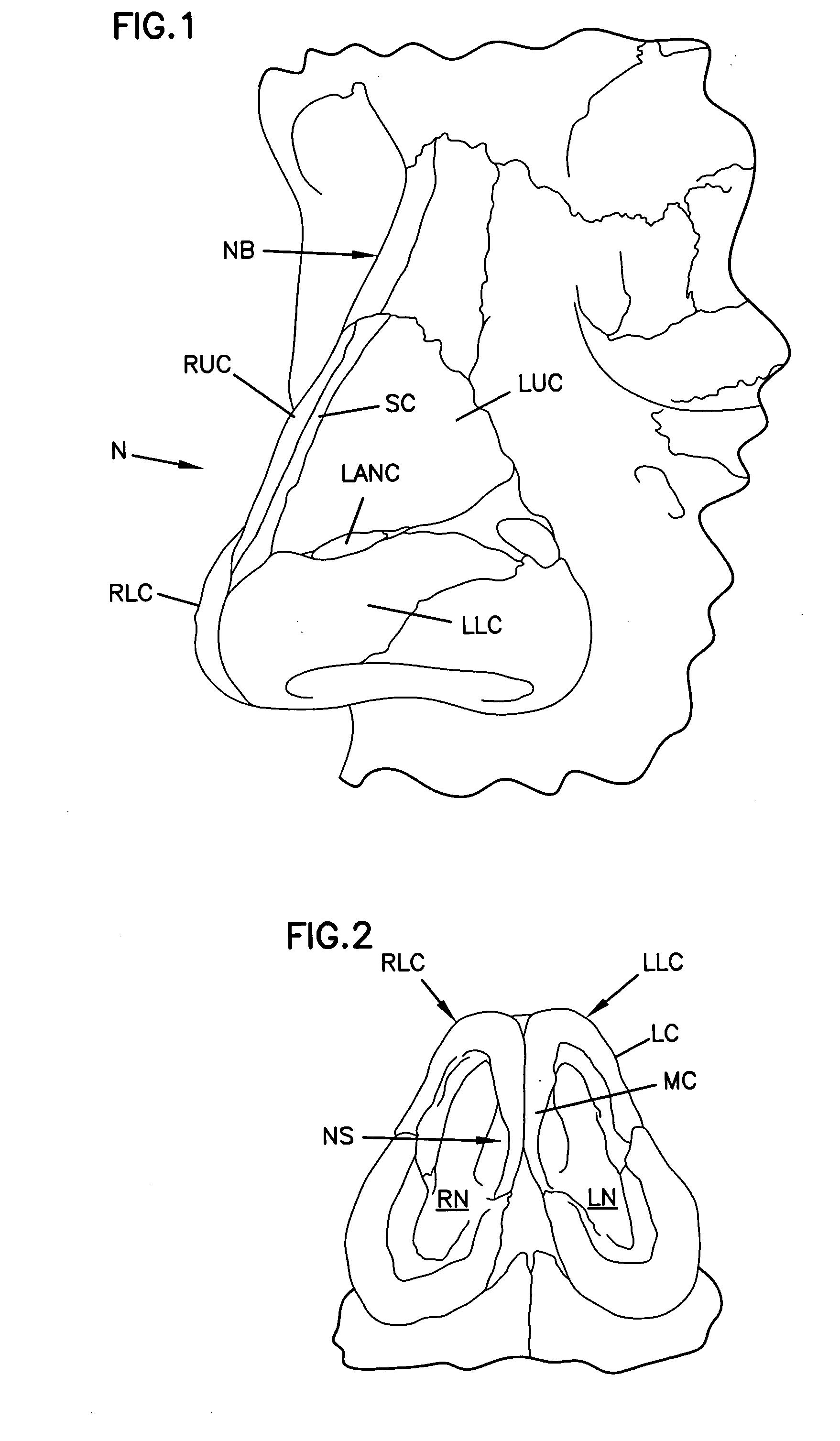
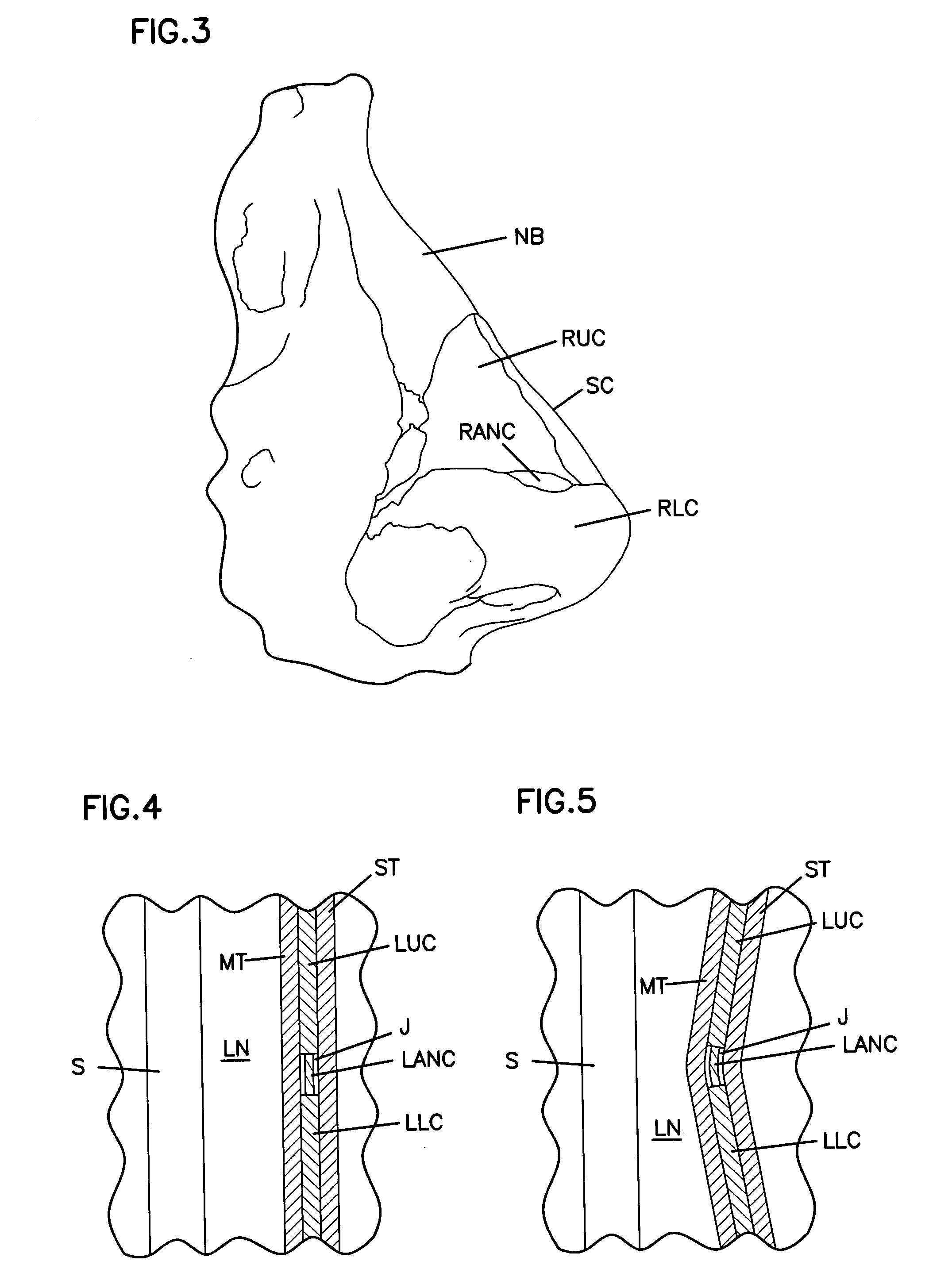
[0035] Before proceeding with a description of the apparatus and method of the present invention, a review of relevant anatomy will facilitate an understanding of the present invention. FIGS. 1-3 show in perspective, bottom plan and right side elevation, respectively, components of the nose with skeletal muscle, soft tissue (such as external skin or nasal mucosa) and blood vessels removed.

[0036] The nose N includes nasal bone NB at an upper end of the nose. The bottom of the nose N includes the lower cartilage also referred to as the major alar cartilage. There is both a right lower cartilage RLC and a left lower cartilage LLC, which are generally symmetrical in structure.

[0037] The lower cartilages RLC, LLC include an external component referred to as the lateral ...


PUM


Abstract

A method and apparatus for treating a nasal valve condition include surgically forming an access path to create a pocket on a side of the patient's nose. The pocket is positioned between a soft tissue layer and opposing surfaces of upper and lower cartilages of the nose. The pocket spans a junction between the upper and lower cartilages. An implant is selected having a length, width and thickness sized to reside within the pocket. The length is sized to span the junction. The width is sized to be less than the width of the upper and lower cartilages. The thickness of the implant is as thin as possible while maintaining material strength to resist bending in response to inhalation pressures at the nasal valve. The implant is placed through the access path into the pocket with the length oriented spanning the junction. A delivery system for placement of the implant includes a surgical tool for forming the access path and for delivering the implant into the access path.

Description

I. BACKGROUND OF THE INVENTION [0001] 1. Field of the Invention [0002] This invention pertains to a treatment method and apparatus for treating a nasal valve. More particularly, this invention pertains to a method and apparatus for treating a nasal valve collapse. [0003] 2. Description of the Prior Art [0004] Nasal valve dysfunction is a prevalent medical condition. Nasal valve collapse is due to weakness of the lateral wall of the nose. At the junction of the upper and lower nasal cartilages, this wall moves medially during the inspiratory phase of nasal breathing. [0005] The nasal valve acts as a restriction to nasal airflow. The nasal valve disrupts the laminar flow characteristics of air, which would otherwise insulate the airflow from the mucosa of the nose. The nasal valve imparts an airflow disturbance which performs crucial nasal functions of mixing in the air stream and enhancing the air / mucosa contacts that are essential for effective exchanges of heat, water and contamina...

Claims


Application Information

Patent Timeline
Patent Type & Authority Applications(United States)
IPC IPC(8): A61B17/24A61F2/18
CPCA61B17/24A61F2/186A61B17/3211A61B17/3468A61B2017/00792A61F2230/0006A61F2230/0008A61F2230/008A61F2230/0093A61F2250/0024A61F2250/0025A61F2250/0026A61F2250/0067
Inventor VASSALLO, CHARLESCRITZER, SUSAN L.
Owner MEDTRONIC XOMED INC
Why Eureka
Try Eureka