Power generation control apparatus for internal combustion engine

a technology of power generation control and internal combustion engine, which is applied in the direction of electric generator control, process and machine control, electric devices, etc., can solve the problem that the above-technology does not necessarily obtain a sufficient fuel saving effect, and achieve the effect of safe reduction of fuel consumption, fuel saving effect, and less influence on map accuracy

Inactive Publication Date: 2006-12-07
DENSO CORP
View PDF15 Cites 44 Cited by
  • Summary
  • Abstract
  • Description
  • Claims
  • Application Information

AI Technical Summary

Benefits of technology

[0007] The present invention is made in view of the above matters, and it is an object of the present invention to provide a power generation control apparatus for an internal combustion engine which can safely reduce an increment of fuel consumption due to power generation while securing a required power generation amount.
[0008] In order to achieve the above object, a power generation control apparatus for an internal combustion engine according to an aspect of the present invention comprises a alternator driven by power of the internal combustion engine, a battery which is charged with power generated by the alternator, and a power generation controller for controlling power generation of the alternator, the power generation control apparatus further comprising fuel consumption calculating means which calculates an increment of fuel consumption per unit power generation amount based upon an increment of the fuel consumption and a power generation amo

Problems solved by technology

Therefore, the above technology does not neces

Method used


Image

  • Power generation control apparatus for internal combustion engine
  • Power generation control apparatus for internal combustion engine
  • Power generation control apparatus for internal combustion engine

Examples


first embodiment

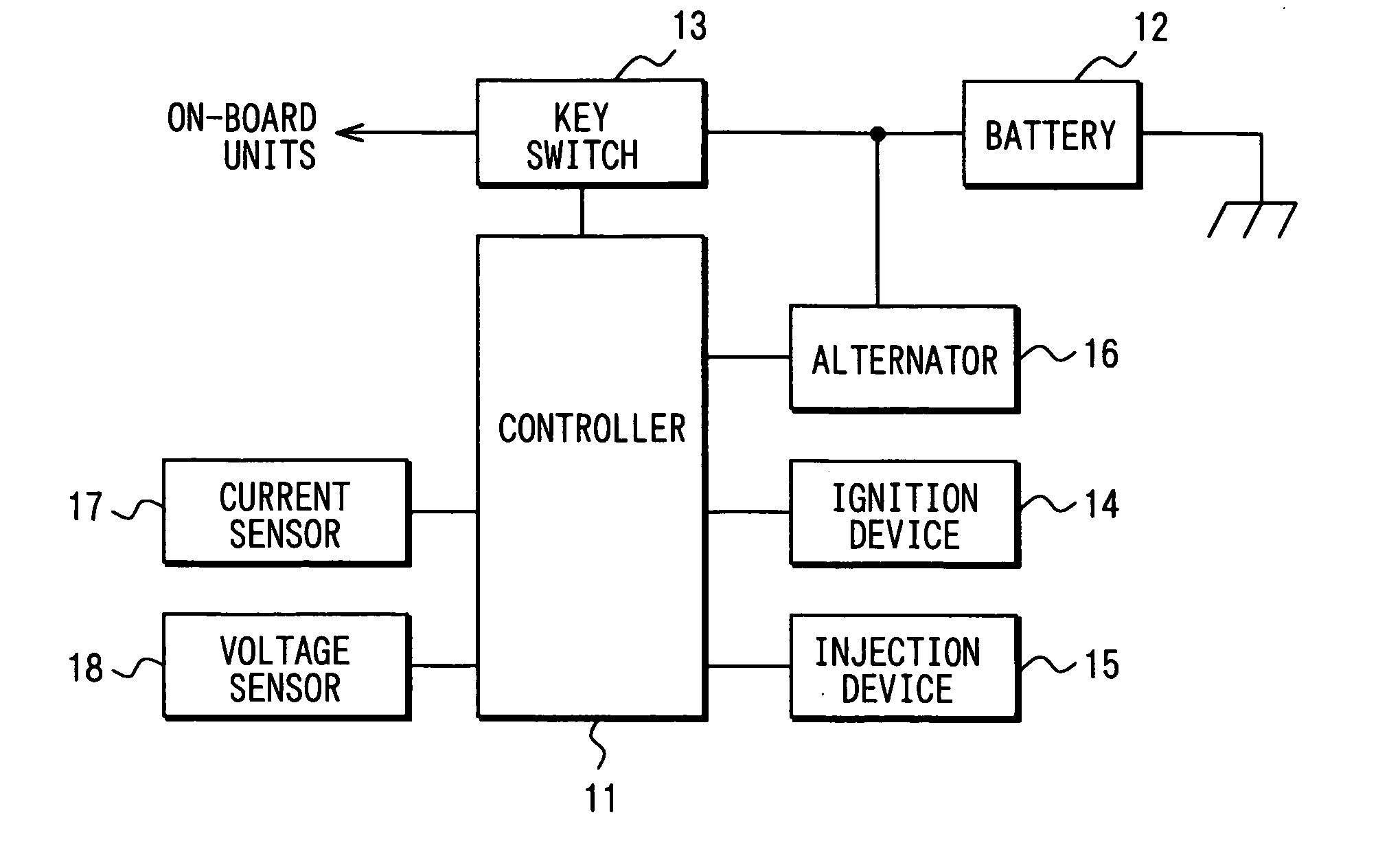
[0054] Referring to FIG. 1, a control device 11 serves as power generation means to which a power source is supplied through a battery 12 and a key switch 13 to control operations of an ignition device 14 and an injection device 15 during engine operating and also to control power generation of an alternator 16. Control of the power generation in the first embodiment will be hereinafter described.

[0055] The control device 11 calculated a charge rate SOC of the battery 12 based upon a charging / discharging current of the battery 12 detected by a current sensor 17 (current detector) and / or an open terminal voltage of the battery 12 detected by a voltage sensor 18 (voltage detector). For example, the control device 11 detects the charging / discharging current of the battery 12 with the current sensor 17 (current detector) and integrates the detection values. On this occasion, a charging current of the battery 12 is set as a plus value and a discharging current of the battery 12 is set a...

second embodiment

[0094] The calculating routine for the electric consumption, the accumulating routine for the electric consumption, the calculating routine for the electric consumption class data, the calculating routine for the average consumption power and the calculating routine for the target electric consumption, similar to the first embodiment are executed. Thereafter, the following routine is executed.

[0095] [Calculating Routine for Correction Amount of Target Electric Consumption]

[0096] A calculating routine for a correction amount of target electric consumption in FIG. 8 is executed in a predetermined cycle (for example, 8 ms cycle) during engine operating and a correction amount of the target electric consumption TCFCcmp is calculated as follows. When this routine is activated, first at Step 2501, the I term (integral term) correction amount I cmp (i) is calculated according to the following equation for performing feedback correction on the target electric consumption TCFC in such a man...

third embodiment

[0103] In the second embodiment, a reference point of the charge / discharge balance of the battery 12 is set as zero. However, In a third embodiment of the present invention shown in FIGS. 10 and 11, a reference point of the charge / discharge balance of the battery 12 is to be corrected in accordance with a charge / discharging amount required for making the SOC of the battery 12 be equal to a target SOC.

[0104] A calculating routine for a correction amount in the reference point of the charge / discharge balance in FIG. 10 is executed in a predetermined cycle (for example, 8 ms cycle) during engine operating. When this routine is activated, first at Step 2701, a deviation between the present SOC and the target SOC is multiplied by a full charging amount and a battery voltage to calculate a charging / discharging amount required for making the SOC of the battery 12 be equal to the target SOC. The correction amount BALcmp in the reference point of the charge / discharge balance is determined b...


PUM


Abstract

An increment of a fuel consumption rate caused by power generation is determined from a difference in fuel consumption rate between a case of performing power generation of an alternator and a case of stopping the power generation. The increment of the fuel consumption rate is divided by a power generation amount of the alternator to determine an increment of a fuel consumption per unit power generation amount. A use-frequency of the electric consumption is determined and also a possible power generation amount and average consumption power are calculated. A target electric consumption is set based upon the use-frequency, the possible power generation amount and the average consumption power so that the charge and discharge balance of the battery becomes zero. The present electric consumption is compared with the target electric consumption to determine whether or not to perform the power generation of the alternator.

Description

CROSS-REFERENCE TO RELATED APPLICATION [0001] This application is based on Japanese Patent Applications No. 2005-162650 filed on Jun. 2, 2005, No. 2005-162651 filed on Jun. 2, 2005, No. 2005-215730 filed on Jul. 26, 2005, No. 2005-215731 filed on Jul. 26, 2005, No. 2005-215732 filed on Jul. 26, 2005, No. 2005-229036 filed on Aug. 8, 2005, the disclosures of which are incorporated herein by reference. FIELD of THE INVENTION [0002] The present invention relates to a power generation control apparatus which controls an alternator in consideration of an increment of fuel consumption caused by power generation of the alternator. BACKGROUND OF THE INVENTION [0003] An alternator mounted on a vehicle is, in many cases, controlled in such a manner that a control current (field current) of the alternator is controlled to control a power generation amount for preventing the battery from being in lack of charge due to checking a charging state of the battery. (refer to JP-2000-4502A and JP-2001...

Claims


Application Information

Patent Timeline
IPC IPC(8): H02P9/04
CPCH02J7/1446H02P2101/45Y02T10/92H02P9/48B60L3/12B60L15/20B60L2250/16B60L2260/42B60L2260/52B60L2260/54B60L50/16B60L58/15Y02T10/64Y02T10/70Y02T10/7072Y02T10/72
Inventor YAMASHITA, YUKIHIRO
Owner DENSO CORP
Why Eureka
Try Eureka