Feeder tube for bar feeder

Inactive Publication Date: 2006-12-14
BARLOAD MACHINE
View PDF8 Cites 11 Cited by
  • Summary
  • Abstract
  • Description
  • Claims
  • Application Information

AI Technical Summary

Benefits of technology

[0008] The present invention has been accomplished under the circumstances in view. It is one object of the present invention

Problems solved by technology

The toxic gas causes an environment pollution problem.
Further, frequently rotating a bar material 93 in the feeder tube 92 may cause supporting blocks 95 to wear or to break.
When some supporting blocks 95 are damaged, all the supporting blocks 95 and the epoxy resin 96 must be removed from the holder base 94 for a replacement, resulting in a big loss.
Further, because a lubricating oil must be applied to the supporting blocks 95 a

Method used


Image

  • Feeder tube for bar feeder
  • Feeder tube for bar feeder
  • Feeder tube for bar feeder

Examples


Embodiment Construction

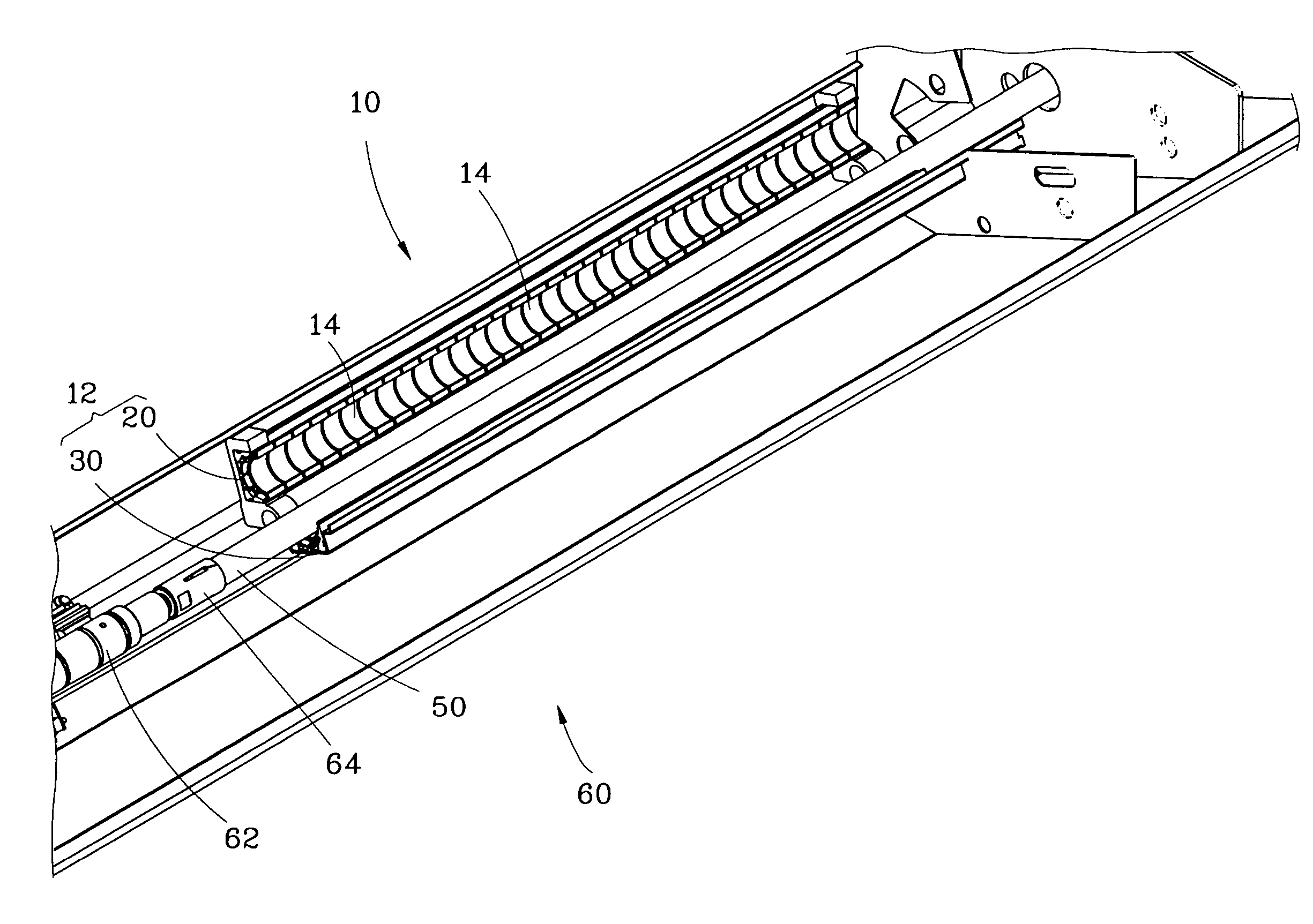
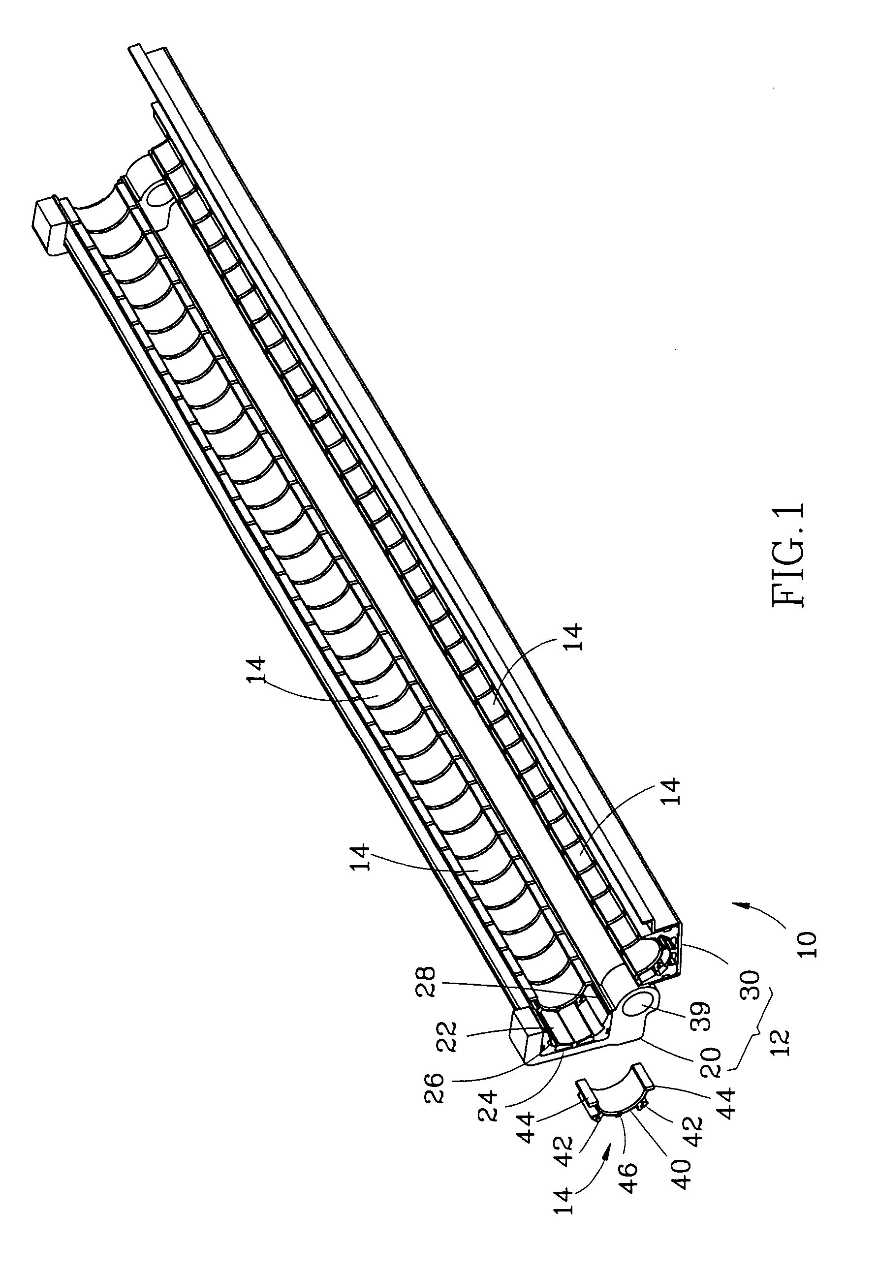
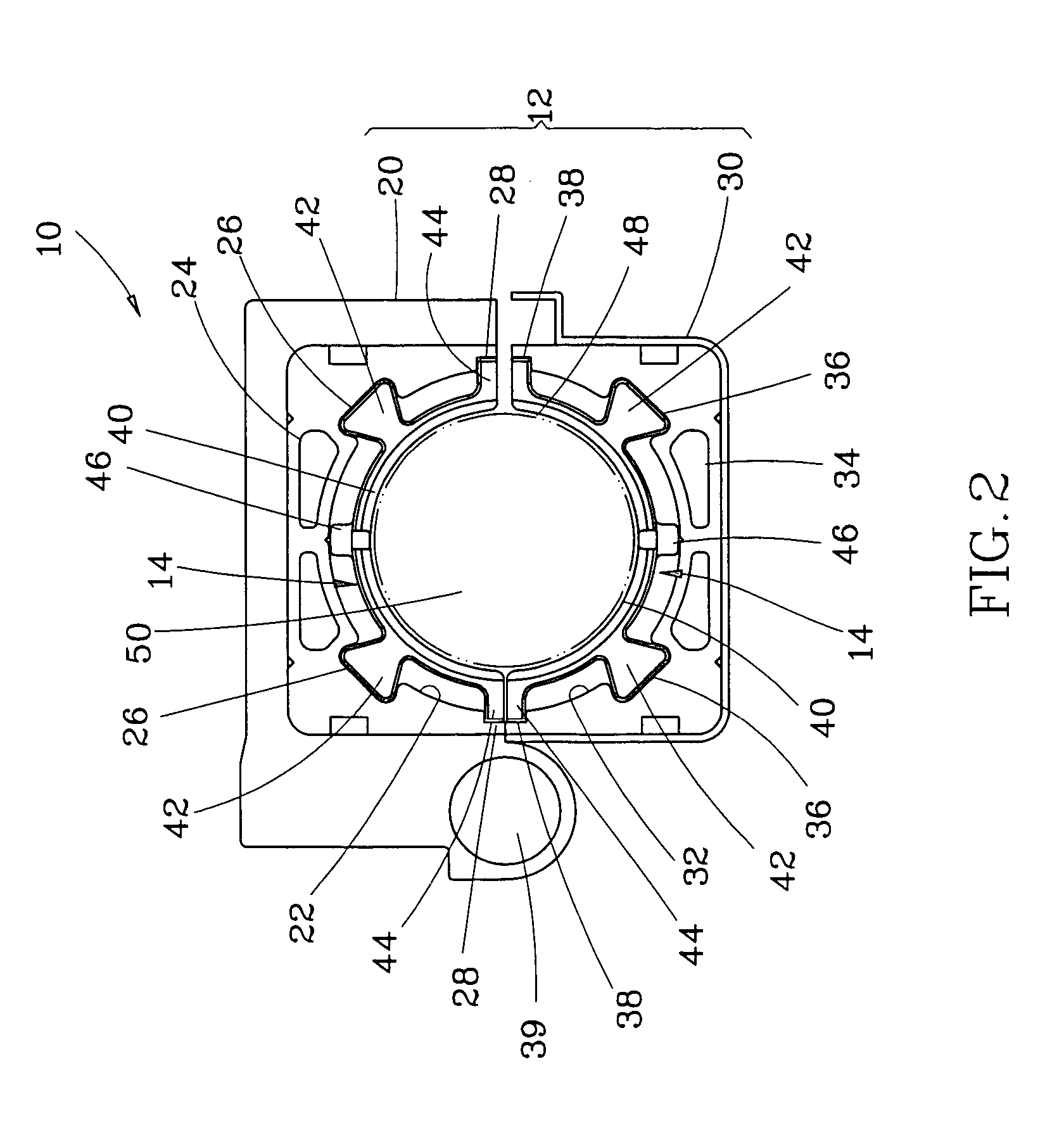
[0022] As shown in FIGS. 1 and 2, a feeder tube 10 for use in a bar feeder in accordance with a first preferred embodiment of the present invention comprises a holder base 12 and a plurality of support members 14.

[0023] The holder base 12 comprises two elongated holder members, namely, the first holder member 20 and the second holder member 30. The first holder member 20 and the second holder member 30 are respectively extruded from aluminum, each having a longitudinal guide wall 22 or 32, and two longitudinal oil holes 24 or 34 cut through the ends. The longitudinal guide walls 22 and 32 have a cross section shaped like a semicircular arc. Each longitudinal guide wall 22 or 32 has two first recessed retaining portions 26 or 36 and two second recessed retaining portions 28 or 38. The first recessed retaining portion 26 or 36 and the second recessed retaining portion 28 or 38 extend along the length of the respective longitudinal guide wall 22 or 32. The two second recessed retainin...


PUM

PropertyMeasurementUnit
Lengthaaaaaaaaaa
Shapeaaaaaaaaaa

Abstract

For use in a bar feeder, a feeder tube is disclosed to include a holder base and a plurality of support members. The holder base has two hinged holder members each having retaining portions. Each support member has positioning portions respectively detachably engaged with the retaining portions of the holder members, and a bearing portion. The bearing portions of the support members define a cylindrical accommodation space for receiving a bar material therein when the two holder members are close.

Description

BACKGROUND OF THE INVENTION [0001] 1. Field of the Invention [0002] The present invention relates to a bar feeder and specifically, to a feeder tube for bar feeder. [0003] 2. Description of the Related Art [0004] In a conventional bar feeder and lathe system, as shown in FIGS. 9 and 10, the bar feeder 90 is provided at the rear side of the automatic lathe 91. The bar feeder 90 has a feeder tube 92, which holds a bar material 93. The bar feeder 90 has a push rod (not shown) controlled to push the bar material 93 toward the automatic lathe 91 for processing. [0005] The aforesaid feeder tube 92 comprises a holder base 94 and a plurality of supporting blocks 95. The supporting blocks 95 are bonded to the holder base 94 with epoxy resin 96. Because the supporting blocks 95 surround the periphery of the bar material 93, the supporting blocks 95 support smooth rotation of the bar material 93 in the feeder tube 92 when the bar material 93 is rotationally forwarding to the lathe 91. [0006] A...

Claims


Application Information

Patent Timeline
IPC IPC(8): B23B13/00
CPCY10T82/2521B23B13/00
Inventor KUO, CHIH-HSIUNG
Owner BARLOAD MACHINE
Why Eureka
Try Eureka