
Rotary electric machine with a stator core made of magnetic steel sheets and the stator core thereof

a technology of stator core and magnetic steel sheet, which is applied in the direction of dynamo-electric machines, magnetic circuit rotating parts, and shape/form/construction of magnetic circuits, etc. it can solve the problems of degrading the magnetic characteristics of the stator core, inevitably increasing the magnetic resistance at an area of each butted surface, and inevitably adding compressive stress to each core sheet along the plane directions. , to achieve the effect of convenient fixation

Inactive Publication Date: 2006-12-14
DENSO CORP
View PDF5 Cites 69 Cited by
  • Summary
  • Abstract
  • Description
  • Claims
  • Application Information

AI Technical Summary

Benefits of technology

[0013] An object of the present invention is to provide, with due consideration to the drawbacks of the conventional machine, a rotary electric machine wherein a manufacturing process of the machine is simplified while improving magnetic characteristics of a stator core when the machine has a large number of circular arc-shaped core sheets laminated along its axial direction and butted to one another along its circumferential direction on each plane perpendicular to the axial direction.
[0015] In this arrangement, although the sheet units are laminated along the axial direction such that positions of the butted surfaces of each core sheet differs, in the circumferential direction, from those of other core sheets which are disposed to be away from the each core sheet by a predetermined number of sheet units along the axial direction, each of the fixing holes in each sheet unit is aligned with a group of fixing holes in the other sheet units along the axial direction. Therefore, each of the fixing members can easily penetrate through the aligned fixing holes of the respective sheet units along the axial direction, so that positions of the core sheets are determined by the fixing members in both the circumferential direction and a radial direction perpendicular to the circumferential and axial directions. Further, positions of the core sheets can be reliably determined by the fixing members fixed to the housing along the axial direction. Accordingly, the core sheets can be easily and reliably fixed to the housing in the stator core.
[0017] Therefore, although positions of the butted surfaces of each core sheet in the circumferential direction differs from those of other core sheets which are disposed to be away from the each core sheet by a predetermined number of sheet units along the axial direction, each of fixing members can easily be inserted into a group of aligned fixing holes along the axial direction. Accordingly, when the fixing members are fixed to a housing of the machine, the core sheets of the stator core can be reliably and easily fixed to the housing.

Problems solved by technology

Further, magnetic resistance at an area of each butted surface inevitably becomes large.
However, when the partial cores are fixed by the housing, a compressive stress is inevitably added to each core sheet along the plane directions.
Therefore, there is high possibility that magnetic characteristics of the stator core are degraded due to distortion of the core sheets caused by the excessive compressive stress.
Further, because a large-scaled motor housing surrounding each partial core is required to be heated at a high temperature in the shrinkage fitting, the manufacturing process of the machine is undesirably complicated.
As a result, rotational force obtained in the machine is undesirably reduced, or iron loss is undesirably increased.
However, accuracy in shaping end surfaces of core sheets and punching quality for holes are not so high.
Therefore, when a large number of core sheets are actually manufactured, holes are inaccurately positioned in the core sheets, end surfaces of core sheets have no predetermined shape, or holes of the core sheets have no predetermined shapes.
The open space undesirably induces the increase of a magnetic resistance of the sheet cores or the reduction of a saturated amount of magnetic flux.
When the core sheets overlap each other, it is required to grind the end surfaces of the core sheets, so that a manufacturing cost of the stator core is undesirably increased.
However, in this case, each core member has holes not receiving pins, so that a manufacturing process of the machine is complicated so as to increase a manufacturing cost of the stator core.

Method used


Image

  • Rotary electric machine with a stator core made of magnetic steel sheets and the stator core thereof
  • Rotary electric machine with a stator core made of magnetic steel sheets and the stator core thereof
  • Rotary electric machine with a stator core made of magnetic steel sheets and the stator core thereof

Examples


embodiment 1

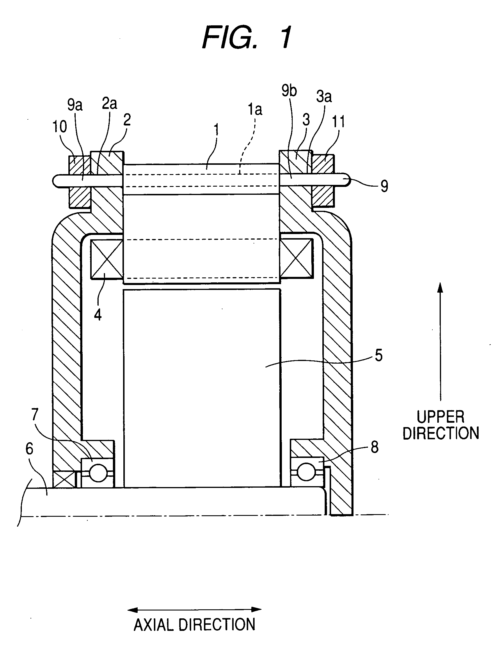
[0036]FIG. 1 is a longitudinal sectional view of a rotary electric machine for a vehicle according to first to tenth embodiments of the present invention. As shown in FIG. 1, a rotary electric machine such as an electric motor or a generator has a stator core 1 formed substantially in a cylindrical shape, a front housing 2 formed substantially in a shape of a shallow dish, a rear housing 3 formed substantially in a shape of another shallow dish, a stator coil 4 wound on the core 1 to generate a magnetic field in the core 1 in response to an alternating current or to generate an alternating current, a rotary shaft 6 being rotatable on a center axis of the core 1, and a rotor 5 disposed in a hollow space of the core 1 and being rotatable around the shaft 6 to be rotated with the shaft 6 or to rotate the shaft 6 according to an electromagnetic interaction with the core 1. The core 1 will be described in second to tenth embodiments in detail.

[0037] The machine further has bearings 7 an...

embodiment 2

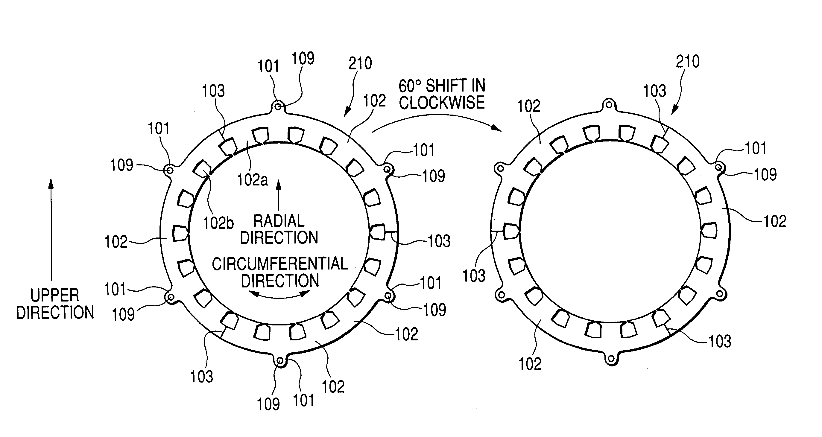
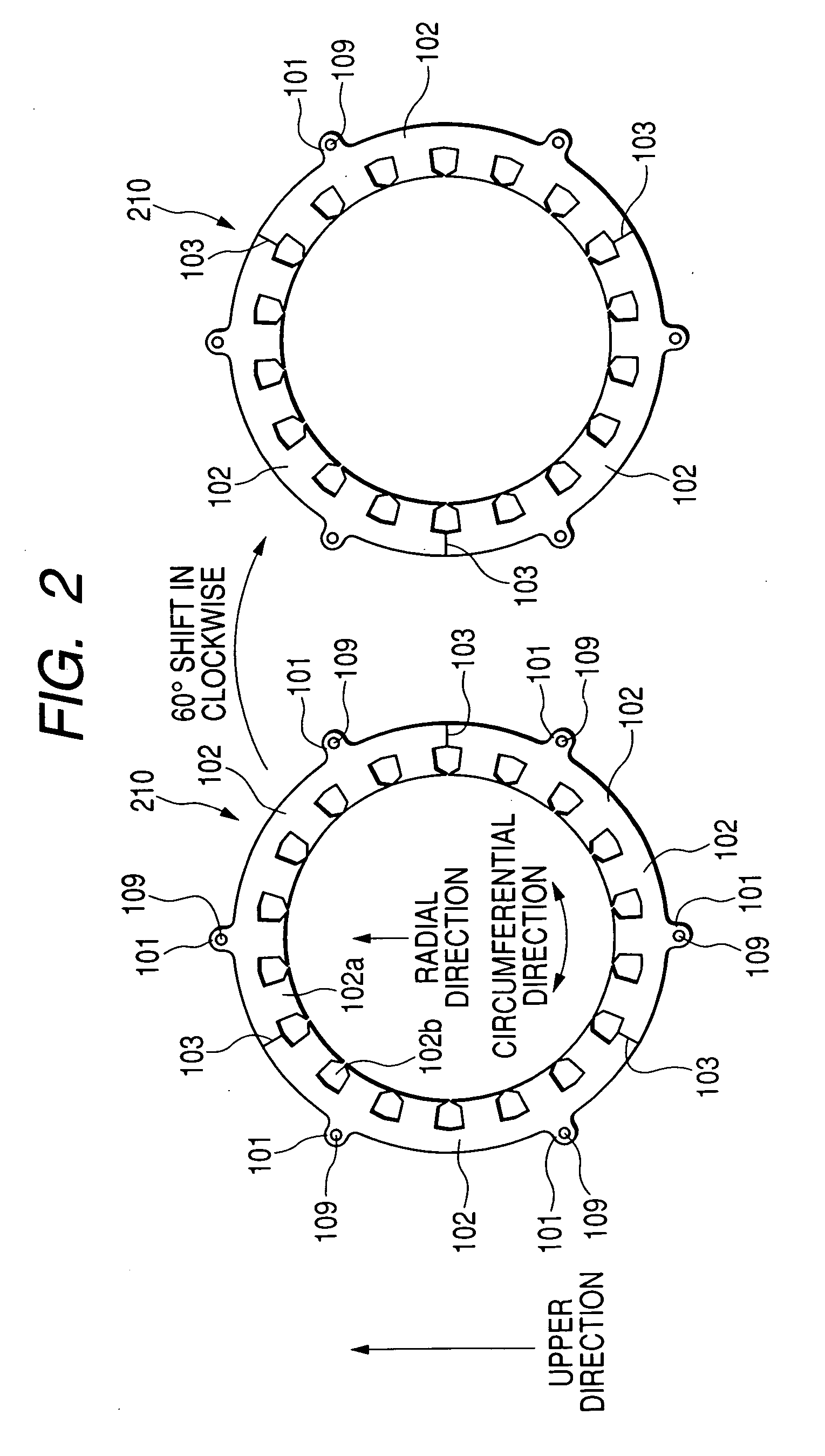
[0063]FIG. 4 is a plan view of three ring-shaped sheet units in the stator core 1 according to a second embodiment.

[0064] A first ring-shaped sheet unit 220 of a first orientation shown on the left side in FIG. 4, a second ring-shaped sheet unit 220 of a second orientation shown on the middle in FIG. 4 and a third ring-shaped sheet unit 220 of a third orientation shown on the left side in FIG. 4 have the same shape as one another. The units 220 of the three orientations are cyclically laminated along the axial direction while keeping the orientations of the units 220 shown in FIG. 3, and the core 1 is formed. That is, each unit 220 of the first orientation occupies the (3N-2)-th layer (N is a natural number), each unit 220 of the second orientation occupies the (3N-1)-th layer, and each unit 220 of the third orientation occupies the 3N-th layer.

[0065] Each unit 220 has three first circular arc-shaped core sheets 104 and three second circular arc-shaped core sheets 105 alternately ...

embodiment 3

[0071]FIG. 5 is a plan view of three types ring-shaped sheet units in the stator core 1 according to a third embodiment.

[0072] A first type ring-shaped sheet unit 230A shown on the left side in FIG. 5 has six circular arc-shaped core sheets 106 made of magnetic steel. A second type ring-shaped sheet unit 230B shown on the middle in FIG. 5 has the six core sheets 105. A third type ring-shaped sheet unit 230C shown on the right side in FIG. 5 has six circular arc-shaped core sheets 107. The six sheets in each type unit are disposed along its circumferential direction to be butted to one another through butted surfaces 103. The three units 230A, 230B and 230C are cyclically laminated along the axial direction so as to align a group of holes 106 of the units along the axial direction and form the core 1.

[0073] The sheets 106 differ from the sheets 105 in that each sheet 106 has one attaching portion 101 shifted by 20 degrees in counterclockwise from that of the sheet 105. The sheets 1...


PUM


Abstract

A rotary electric machine has a housing and a stator core and a plurality of fixing members. The core has sheet units laminated along an axial direction. Each unit has core sheets disposed along a circumferential direction so as to be butted to one another on butted surfaces of the sheets. Each position of the butted surfaces of each sheet in the circumferential direction differs from any of those of other sheets adjacent to the each sheet along the axial direction. The sheets of each unit have a plurality of fixing holes disposed along the circumferential direction such that each hole in each unit is aligned with a group of holes in the other units along the axial direction. Each of the members penetrates through a group of aligned holes of the units along the axial direction and is fixed to the housing.

Description

CROSS-REFERENCE TO RELATED APPLICATION [0001] This application is based upon and claims the benefit of priority of the prior Japanese Patent Application 2005-168737 filed on Jun. 8, 2005, and the prior Japanese Patent Application 2006-45545 filed on Feb. 22, 2006 so that the contents of which are incorporated herein by reference. BACKGROUND OF THE INVENTION [0002] 1. Field of the Invention [0003] The present invention generally relates to a rotary electric machine wherein a stator core having magnetic steel sheets butted to one another and laminated and a coil-wound on the stator core electromagnetically interact with a rotor to convert rotational force of the rotor to electric power or to convert electric power supplied to the coil to rotational force. [0004] 2. Description of Related Art [0005] A conventional rotary electric machine having magnetic steel core sheets combined with one another and laminated has been proposed in Published Japanese Patent First Publication No. 2001-21...

Claims


Application Information

Patent Timeline
IPC IPC(8): H02K1/00H02K1/06H02K1/28H02K1/18
CPCH02K1/16H02K1/148
Inventor YOSHINAGA, SOICHIYONEDA, SHIGENORI
Owner DENSO CORP
Features
  • Generate Ideas
  • Intellectual Property
  • Life Sciences
  • Materials
  • Tech Scout
  • Unparalleled Data Quality
  • Higher Quality Content
  • 60% Fewer Hallucinations
Learn More