Image projection apparatus

a technology of image projection and projection light, which is applied in the field of image projection light apparatus, can solve the problems of inability to display correct gradation, and rapid drop of light emission amount, and achieve the effect of preventing deterioration of color characteristics

Inactive Publication Date: 2006-12-14
OLYMPUS CORP
View PDF7 Cites 82 Cited by
  • Summary
  • Abstract
  • Description
  • Claims
  • Application Information

AI Technical Summary

Benefits of technology

[0015] In consideration of the heretofore known problems described above, an object of the present invention is to provide an image projection apparatus that allows a selection of one of two modes: a mode that prioritizes brightness; and a mode for obtaining the color excellence of an LED, while ensuring a sufficient light amount, and preventing deterioration in color characteristics due to light amount variation.

Problems solved by technology

However, the light emission amount of an LED changes depending on the temperature of the light emitting element, and the light emission amount rapidly drops as temperature rises.
However, when the light amount of the illumination light changes, the correct gradation cannot be displayed.
However, in the case of using an LED as a light source, if the LED is driven by a constant pulse current, a problem occurs in that the light amount of the illumination light varies, and the gradation cannot be displayed correctly by the DMD.
Accordingly, since the average light emission amount of an LED can be maximized when the LED is driven by a constant pulse current, this is effective in that the LED projector, which has considerably less light amount than a conventional lamp projector, can be used more brightly However, since gradation expression cannot be correctly performed, color shift occurs in half tone gradation, and hence excellence in color, which is another advantage of having LEDs as a light source, is impaired.

Method used


Image

  • Image projection apparatus
  • Image projection apparatus
  • Image projection apparatus

Examples


first embodiment

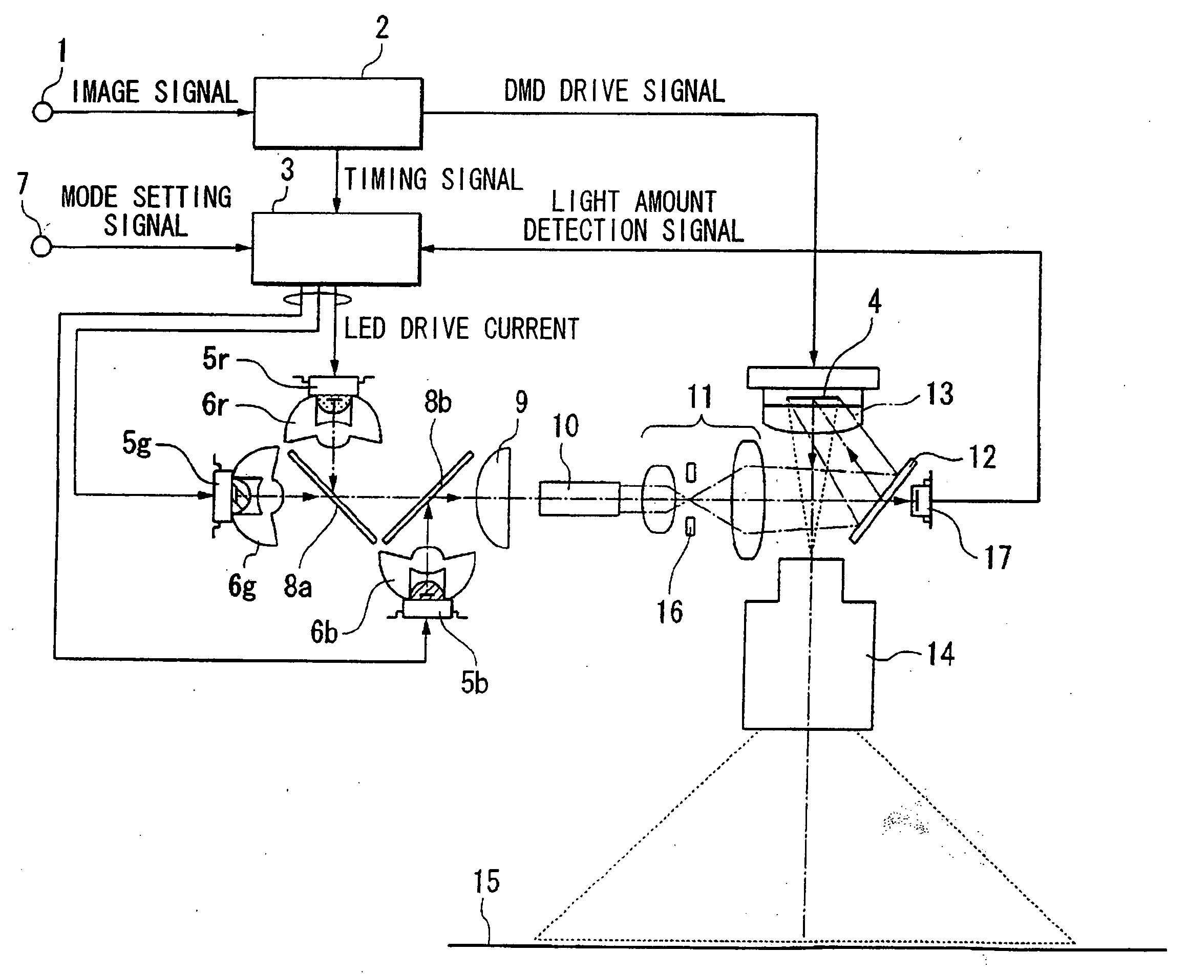
[0053]FIG. 1 shows a first embodiment of a projector to which the present invention is applied. In FIG. 1, an image signal is supplied to an input terminal 1. The image signal from the input terminal 1 is supplied to a DMD drive control circuit 2. The DMD drive control circuit 2 converts the input image signal into an RGB field sequential DMD driving signal, and outputs this field sequential DMD driving signal to a DMD element 4.

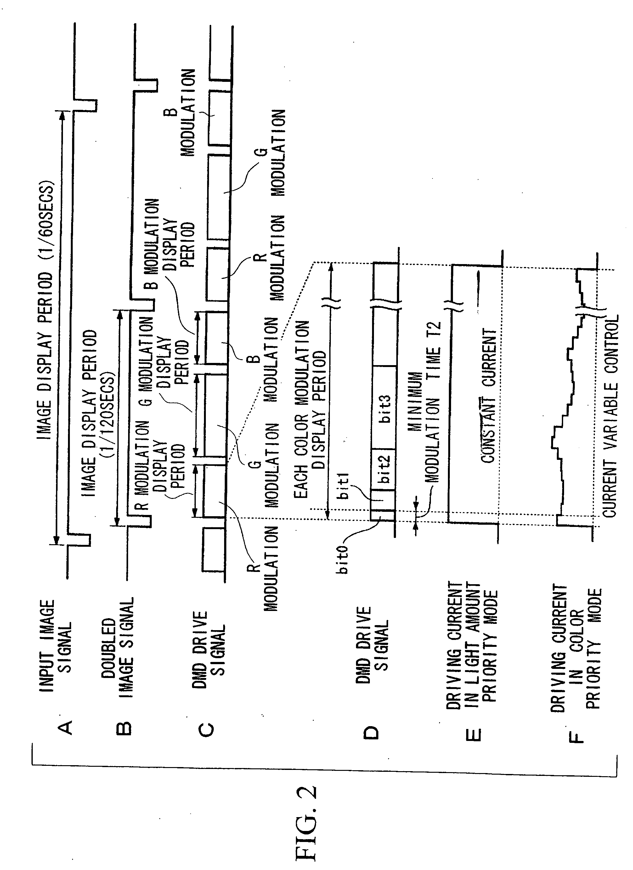
[0054] That is to say, as shown in A of FIG. 2, one period T0 of the input image signal is, for example, 1 / 60 seconds in the case of NTSC format. This input image signal is doubled as shown in B of FIG. 2 in order to prevent color breakup. One period T1 of a doubled DMD driving signal is, for example, 1 / 120 seconds, and this becomes an image display period. Within the image display period T1 of each DMD driving signal, the R modulation display period, B modulation display period, and G modulation display period are set as shown in C of FIG. 2. As shown in D...

second embodiment

[0098]FIG. 10 shows a second embodiment of a projector to which the present invention is applied. In this example, a plurality of the LEDs are arranged in a circle, and a rotation optical system that switches the LEDs with a rotation rod is used.

[0099] In FIG. 10, an image signal is supplied to an input terminal 101. The image signal from the input terminal 101 is supplied to a DMD drive control circuit 102. The DMD drive control circuit 102 converts the input image signal into an RGB field sequential DMD driving signal, and outputs this RGB field sequential DMD driving signal to a DMD element 104. Moreover, a timing signal that synchronizes with the field sequential driving signal is generated in the DMD drive control circuit 102. This timing signal is supplied to the light source drive control circuit 103.

[0100] The DMD element 104 is a spatial light modulation element that has a large number of minute mirrors disposed on the surface thereof, the angles of the mirrors being chan...


PUM


Abstract

There is provided An image projection apparatus comprising: a spatial light modulation element that modulates illumination light by switching the display and non-display statuses of the respective pixels based on pulse width modulation driving to perform gradation expression for each pixel; a light source section able to increase and decrease the amount of illumination light output according to an input controlled variable; a light source control section that periodically controls the light amount of the illumination light output from the light source section; and a projection optical section that projects images modulated by the spatial light modulation element, wherein the light source control section selectively controls the light amount of the illumination light output from the light source section by either one of a first mode in which the controlled variable is changed in a first control period that is shorter than the display period for the spatial light modulation element to display the input image information, and a second mode in which the controlled variable is changed in a second control period that is longer than the first control period.

Description

BACKGROUND OF THE INVENTION [0001] 1. Field of the Invention [0002] The present invention relates to an image projection apparatus that displays an image of multiple gradations by pulse-width modulating (PWM) light illuminated on an image modulation device for each pixel, and in particular, to one that maintains a required light amount while improving color characteristics of the image. [0003] This application is based on Japanese Patent Application No. 2005-172156, the content of which is incorporated herein by reference. [0004] 2. Description of Related Art [0005] In recent years, light emitting diodes (hereinafter referred to as “LEDs”), which are one type of semiconductor light source, have drawn attention as an alternative light source to light bulbs. The advantages of LEDs such as small size, greater durability, longer operating life, and lower power consumption have received much attention, and LEDs have been used as an alternative to lamps for indicators and the like. Howeve...

Claims


Application Information

Patent Timeline
Patent Type & Authority Applications(United States)
IPC IPC(8): G03B21/20
CPCG02B26/0816H04N5/7458H04N9/3114H04N9/3155G03B21/206G03B21/2013G03B21/2033G03B21/2053H04N9/3197
Inventor TANI, NAOAKI
Owner OLYMPUS CORP
Why Eureka
Try Eureka