Optical pickup device

a pickup device and optical technology, applied in the field of optical pickup devices, can solve the problems of inefficient laser light reflection on the splitting surface of p-, ineffective laser light for cd, and inability to efficiently perform laser light for p-, so as to improve the light use efficiency and improve the use efficiency of laser light. , the effect of avoiding the formation of film on the splitting surfa

Inactive Publication Date: 2006-12-14
SANYO ELECTRIC CO LTD
View PDF3 Cites 0 Cited by
  • Summary
  • Abstract
  • Description
  • Claims
  • Application Information

AI Technical Summary

Benefits of technology

[0018] Accordingly, light use efficiency of the laser light from the first laser source arranged on the transmitting side of the polarizing beam splitter can be enhanced while ensuring light use efficiency of the laser light emitted from the second laser source arranged on the reflecting side of the polarizing beam splitter. As a result, it is possible achieve a desirable configuration in which the first laser source arranged on the transmitting side of the polarizing beam splitter, which is relatively advantageous in terms of optical axis deviation, is caused to function in correlation with a signal recording medium having higher density.
[0020] Accordingly, light use efficiency of the laser light from the first laser source arranged on the transmitting side of the polarizing beam splitter can be enhanced while ensuring light use efficiency of the laser light emitted from the second laser source arranged on the reflecting side of the polarizing beam splitter, such that it is possible to configure the first laser source arranged on the transmitting side of the polarizing beam splitter, which is relatively advantageous in terms of optical axis deviation, to function in correlation with a signal recording medium having higher density. Further, by providing the above-noted film characteristic, the splitting surface of the polarizing beam splitter exhibits substantial transmission of s-polarization component with respect to the laser light of the first wavelength emitted from the first laser source while exhibiting substantial reflection of s-polarization component with respect to the laser light of the second wavelength emitted from the second laser source. According to the above-noted film characteristic, although the splitting surface is limited in connection with the laser light of the first wavelength in that the splitting surface must substantially transmit the s-polarization component, no design limitations are created in relation to transmittance of the p-polarization component. Accordingly, it is sufficient to simply configure the splitting surface to substantially transmit both p-polarization and s-polarization components in connection with the laser light of the first wavelength, such that impediments to film formation of the splitting surface are avoided.
[0021] Accordingly, both the laser light of the first wavelength and the laser light of the second wavelength are reflected by the plate-like beam splitter by virtue of s-polarization. Accordingly, light use efficiency can be enhanced for both laser light beams. In addition, the splitting surface of the plate-like beam splitter need simply be characterized to have a reflectance higher than its transmittance, resulting in minimized design limitations of the splitting surface, high freedom in the arrangement angle of the plate-like beam splitter, and cost advantages.
[0022] Accordingly, laser light which has been passed through a quarter-wave plate in both the outgoing and incoming paths is returned to the splitting surface of the polarizing beam splitter with p-polarization being its main component, such that the returned laser light transmits through the polarizing beam splitter. By providing the diffraction filter for diffracting p-polarization between the first laser source and the polarizing beam splitter, it is possible to prevent the returned laser light from interfering with the laser light emitted from the first laser source.
[0023] Moreover, by providing the diffraction filter, the laser light of the second wavelength emitted from the second laser source is prevented from reaching the first laser source. It is therefore possible to prevent the laser light of the second wavelength from being reflected by an end surface of the laser chip of the first laser source and subsequently penetrating back into the outgoing optical system of the laser light of the second wavelength.

Problems solved by technology

Accordingly, at the second beam splitter, when the device design is determined while giving priority to light use efficiency of one of the laser lights (laser light for DVD, for example), light use efficiency of the other laser light (laser light for CD, for example) is compromised.
The laser light incident on the splitting surface of the second beam splitter in s-polarized state, i.e., the laser light for DVD whose light use efficiency is given priority, is reflected efficiently, while reflection of the laser light incident on the splitting surface in p-polarized state, i.e., the laser light for CD, is not efficiently performed.
This results in increased limitations to freedom in design, as well as cost disadvantages.
Accordingly, when high importance is placed on light use efficiency of the DVD optical system and therefore the laser diode for DVD is arranged on the reflecting side of the polarizing beam splitter, an optical axis deviation due to a tilt of the polarizing beam splitter would cause problems in the DVD optical system which requires higher accuracy in signal recording density as compared to the CD optical system.

Method used


Image

  • Optical pickup device
  • Optical pickup device
  • Optical pickup device

Examples


Embodiment Construction

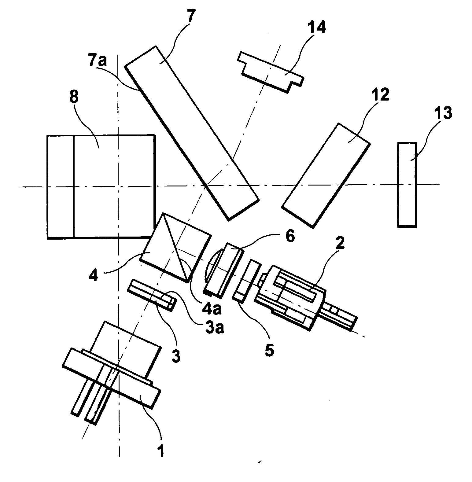
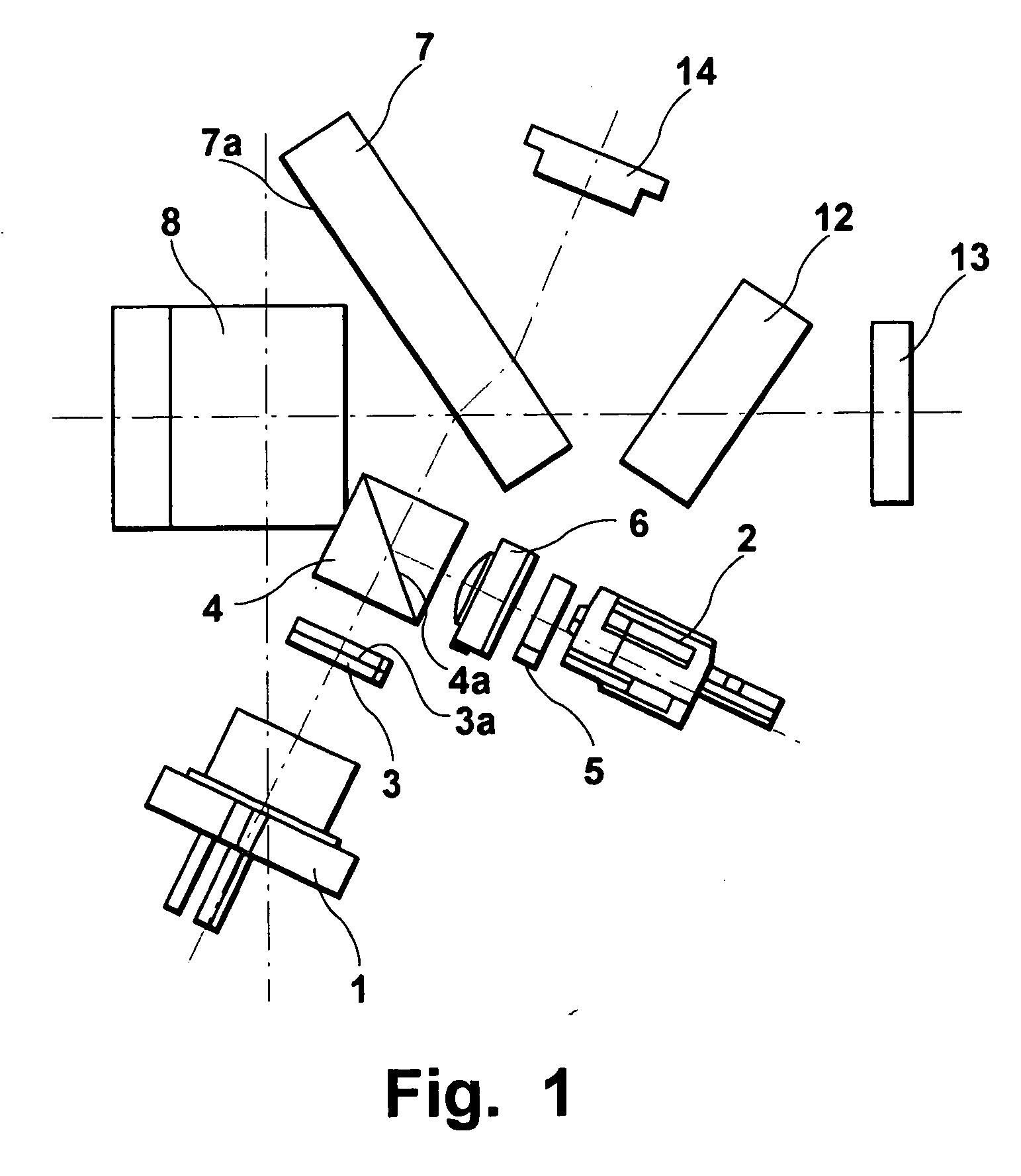
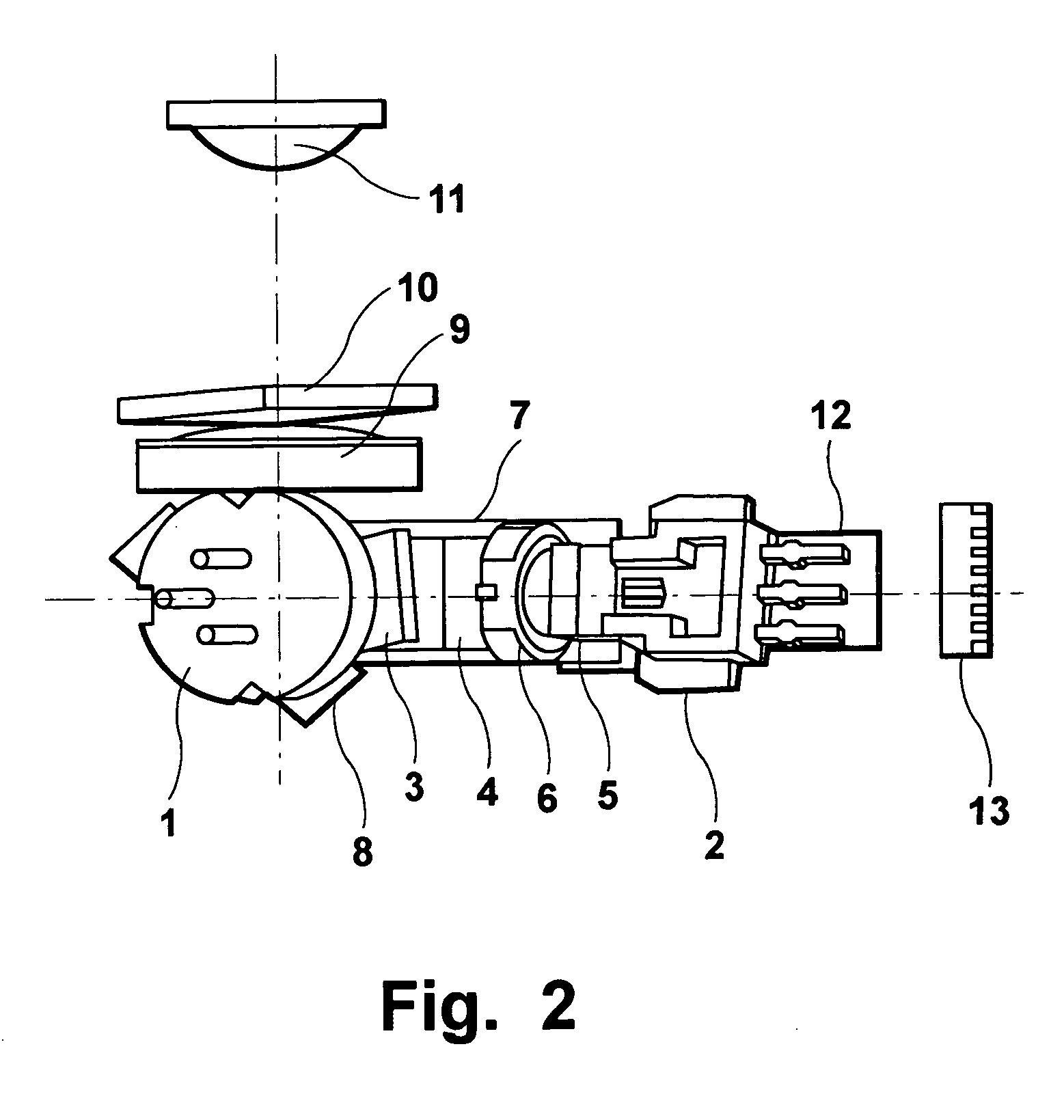
[0029]FIGS. 1 and 2 are plan and side views of an optical arrangement employed in an examplary embodiment of an optical pickup device according to an aspect of the present invention. The optical pickup device shown in FIGS. 1 and 2 is configured to be capable of performing recording and reproduction using CDs as well as DVDs.

[0030] A first can-package type laser diode 1 serving as the first laser source emits laser light having a first wavelength within the range from 650-665 nm (e.g., 660 nm) which is in the red wavelength region and appropriate for performing DVD recording and reproduction. A second frame-package type laser diode 2 serving as the second laser source emits laser light having a second wavelength within the range from 775-795 nm (e.g., 785 nm) which is in the infrared wavelength region and appropriate for performing CD recording and reproduction. The first and the second laser diodes 1, 2 are selectively used in accordance with the disc type. It should be noted that...


PUM

PropertyMeasurementUnit
red wavelengthaaaaaaaaaa
infrared wavelengthaaaaaaaaaa

Abstract

A first laser source is arranged on a transmitting side of a polarizing beam splitter, while a second laser source is arranged on a reflecting side of the polarizing beam splitter. The splitting surface of the polarizing beam splitter has a film characteristic of substantially transmitting s-polarization component of the laser light having the first wavelength emitted by the first laser source and substantially reflecting s-polarization component of the laser light having the second wavelength emitted by the second laser source. A plate-like beam splitter serves to introduce laser light reflected off of a signal recording medium into an optical detector by directing the laser light away from the optical path in which the laser sources are located. The plate-like beam splitter includes a splitting surface which has a reflectance that is higher than its transmittance.

Description

CROSS-REFERENCE TO RELATED APPLICATION [0001] This application claims priority to Japanese Patent Application No. 2005-156941 filed on May 30, 2005, which is incorporated herein by reference in its entirety. BACKGROUND OF THE INVENTION [0002] 1. Field of the Invention [0003] The present invention relates to an optical pickup device including a first laser source which emits laser light having a first wavelength, and a second laser source which is arranged in an optical path apart from that of the first laser source and emits laser light having a second wavelength which differs from the first wavelength. In this optical pickup device, each of the laser light rays emitted from the first and the second laser source is introduced into a common optical path by means of a polarizing beam splitter. The laser light directed into the common optical path is reflected by a plate-like beam splitter so as to be directed through an objective lens. The laser light is then converged by means of the...

Claims


Application Information

Patent Timeline
Patent Type & Authority Applications(United States)
IPC IPC(8): G11B7/00
CPCG11B7/1263G11B7/1275G11B2007/0006G11B7/1365G11B7/1395G11B7/1356
Inventor HOTTA, TOHRUKAWASAKI, RYOUICHINAKAMURA, SHIGERU
Owner SANYO ELECTRIC CO LTD
Why Eureka
Try Eureka