
Apparatus for applying coating solution and method of fabricating liquid crystal display device using the same

a technology of liquid crystal display device and coating solution, which is applied in the direction of photomechanical treatment, chemical vapor deposition coating, paper/cardboard containers, etc., can solve the problems of large amount of energy consumed, large amount of damage to the substrate, and inability to coat a large and heavy fpd substrate, etc., and achieve the effect of improving the internal shape of the nozzl

Inactive Publication Date: 2006-12-21
LG DISPLAY CO LTD
View PDF7 Cites 15 Cited by
  • Summary
  • Abstract
  • Description
  • Claims
  • Application Information

AI Technical Summary

Benefits of technology

The present invention provides an apparatus for applying a coating solution to a large substrate and a method of fabricating a liquid crystal display device using the same. The apparatus includes a nozzle with a controlled distance between the external and internal bodies, an inlet port for receiving the coating solution, and a discharge port for applying the coating solution to the surface of the material to be processed. The method involves coating the substrates with the coating solution, forming a thin film transistor pattern and a color filter pattern on the substrates, and attaching them together. The technical effects include improved uniformity of the coating solution and improved internal shape of the nozzle for arithmetic uniformity.

Problems solved by technology

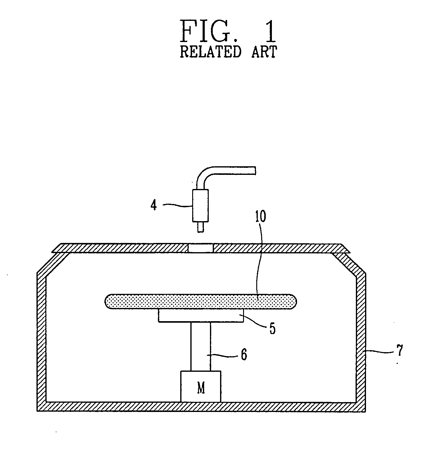
The spray coating method and the roll coating method are not suitable for forming a highly precise pattern in terms of control of uniformity and thickness of a film so that the spin coating method is used for forming the highly precise pattern.
However, it is not suitable for coating a large and heavy FPD substrate such as a glass substrate with a photosensitive material.
This is because it is very difficult to rotate the large and heavy substrate to be coated with the photosensitive material at high speed and the substrate is damaged and a large amount of energy is consumed when the substrate rotates at high speed.
Also, in the spin coating method, since a much larger amount of photoresist is thrown away than the amount of photoresist that is used, photoresist is wasted.
The amount of wasted photoresist is much larger than the amount of the photoresist applied to the substrate to be used for making the substrate photosensitive and the fragments of the scattered photoresist may operate as foreign substances and may contaminate environments.

Method used


Image

  • Apparatus for applying coating solution and method of fabricating liquid crystal display device using the same
  • Apparatus for applying coating solution and method of fabricating liquid crystal display device using the same
  • Apparatus for applying coating solution and method of fabricating liquid crystal display device using the same

Examples


first embodiment

[0058]FIG. 4 schematically illustrates the section of a nozzle according to the present invention.

[0059] As illustrated in FIG. 4, the nozzle 240 includes a first nozzle body 241a, a second nozzle body 241b, an inlet port 246, and a discharge port 242.

[0060] The two nozzle bodies 241a and 241b are coupled with each other to form a nozzle body 241. An accommodating space 244 in which a predetermined amount of photosensitive material is temporarily stored is formed between the first nozzle body 241a and the second nozzle body 241b in order to uniformly apply the photosensitive material pressed by pumping means.

[0061] The inlet port 246 is formed on the second nozzle body 241b to supply the photosensitive material to the accommodating space 244. The discharge port 242 is formed on the bottom surface that faces the substrate in the form of a slit its length is larger than its width to coat the surface of the substrate with the photosensitive material.

[0062] A gap between the first no...

second embodiment

[0064]FIG. 5 schematically illustrates the section of a nozzle according to the present invention, which schematically illustrates the shape of the inside of the nozzle.

[0065] As illustrated in FIG. 5, a nozzle 340 according to the present embodiment includes nozzle bodies 341 and 347, an inlet port 346, and a discharge port 342.

[0066] The nozzle bodies 341 and 347 are divided into an external nozzle body 341 and an internal nozzle body 347. The external nozzle body 341 is divided into a first external nozzle body 341a and a second external nozzle body 341b. The internal nozzle body 347 is divided into a first internal nozzle body 347a and a second internal nozzle body 347b.

[0067] In FIG. 5, the inlet port 346 may be formed between the first nozzle body 341a and the second nozzle body 341b. The inlet port 346 may also be formed on the second nozzle body 341b, similar to the first embodiment.

[0068] Also, the discharge port 342 is formed on the bottom surface of the nozzle 340 that...


PUM

PropertyMeasurementUnit
distanceaaaaaaaaaa
photosensitiveaaaaaaaaaa
areasaaaaaaaaaa

Abstract

An apparatus for applying a coating solution and a method of fabricating a liquid crystal display device using the same are provided. In order to improve the shape of the inside of the nozzle and to secure the geometrical uniformity of the inside of the nozzle, the apparatus includes a nozzle comprising a nozzle body, the nozzle body including an external body and an internal body. A distance between the external body and the internal body is controlled. An inlet port is provided on the nozzle body so that coating solution is received, and a discharge port is provided below the nozzle body to coat the surface of a material to be processed with the coating solution and a driving unit for moving the nozzle in a predetermined direction.

Description

[0001] This application claims the benefit of Korean Patent Application No. 2005-53189, filed on Jun. 20, 2005, which is hereby incorporated by reference for all purposes as if fully set forth herein. BACKGROUND OF THE INVENTION [0002] 1. Field of the Invention [0003] The present invention relates to an apparatus for applying a coating solution. More particularly, the present invention relates to an apparatus for uniformly applying coating solution such as photoresist, development solution, and color filters to the surface of a processed material such as a substrate of a flat panel display (FPD) and a semiconductor wafer and a method of fabricating a liquid crystal display device using the same. [0004] 2. Discussion of the Related Art [0005] A plurality of thin film depositing processes, photolithography processes for exposing a selected region of the thin film, and etching processes of removing the thin film of the exposed region are included in processes of fabricating a flat pane...

Claims


Application Information

Patent Timeline
Patent Type & Authority Applications(United States)
IPC IPC(8): B32B37/00B32B38/00B05B3/00B05B13/02
CPCB05B13/041B05C5/0216Y10T156/10G03F7/162H01L21/6715B05C5/0262G02F1/13
Inventor JEONG, TAE KYUN
Owner LG DISPLAY CO LTD
Learn More