Device and method for electron beam irradiation

a technology of electron beam and device, which is applied in the field of devices and methods for electron beam irradiation, can solve the problems of undesired and/or uncontrollable hygiene levels, increased irradiation device size, and increased irradiation device weight, so as to reduce the risk of recontamination, reduce the energy of x-rays, and minimise the risk of x-rays

Active Publication Date: 2006-12-21
TETRA LAVAL HLDG & FINANCE SA
View PDF13 Cites 20 Cited by
  • Summary
  • Abstract
  • Description
  • Claims
  • Application Information

AI Technical Summary

Benefits of technology

[0019] In an embodiment the web guide comprises a first and a second roller journalled in support members, the rollers being formed and mutually located in such a way that the first roller angles the web the second angle and the second roller angles the web the first angle. These rollers are reliable and relatively cheap.
[0020] In yet another embodiment the entrance segment of the inlet portion and the outlet portion are adjacent the central portion of the tunnel and that the exit segment of the inlet portion and the outlet portion are directed away from each other, thereby further separating the sterilized web from the non-sterilized web and thereby further minimising the risk of any recontamination.
[0021] Advantageously, the tunnel portions and the emitter housing are enclosed in a housing. This makes it easy to encapsulate, control and discharge ozone formed during irradiation.
[0022] Further, the invention refers to a method for electron beam irradiation of at least a first side of a web, the method comprising the steps of: passing the web through a tunnel, said tunnel being provided with a web inlet portion, a web outlet portion and a central portion adapted to receive at least a first electron beam emitter provided with an electron exit window, emitting electrons into the tunnel from the emitter through the electron exit window, and forcing any X-ray being formed by the electrons during irradiation of the web hit the tunnel wall at least twice before exiting the tunnel by forming the tunnel so that it is angled at at least two locations in each of the inlet and outlet portions. Thus, it is provided a way of shielding an irradiation device still making it possible to pass a web through it, and yet minimising the risk of X-rays bein...

Problems solved by technology

However, irradiation with electrons creates unwanted X-rays.
It has been a problem to obtain acceptable radiation levels outside an irradiation device of reasonable size.
Firstly, due to the design of the radiation traps they may cause uncontrollable fluid flows through the irradiation device during sterilisation and cause difficulties during pre...

Method used


Image

  • Device and method for electron beam irradiation
  • Device and method for electron beam irradiation
  • Device and method for electron beam irradiation

Examples


first embodiment

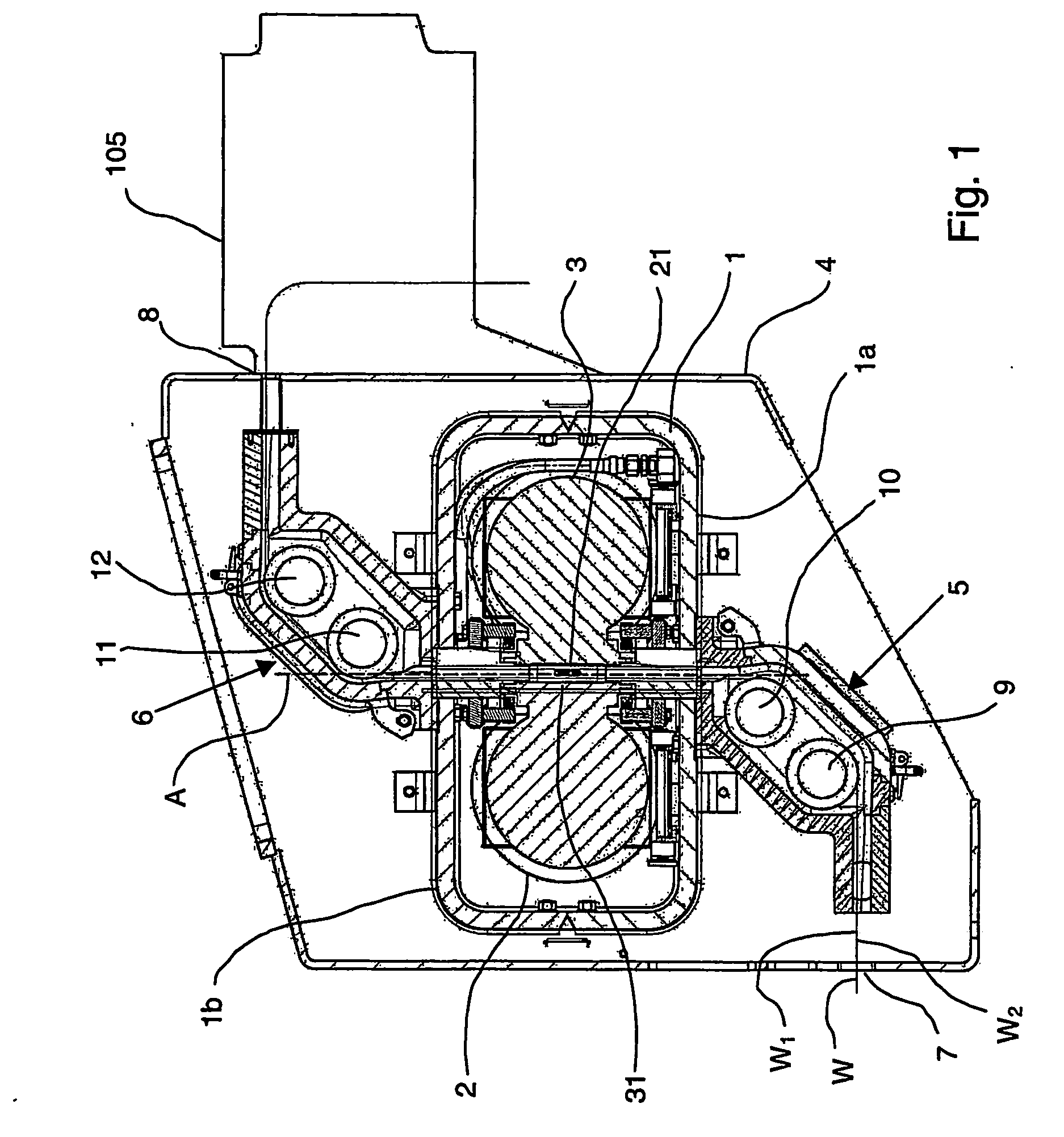
[0046] In the first embodiment there is provided a fluid connection between a web outlet opening 112 of the second chamber 111 and a web outlet opening 121 of the first chamber 107. Thus, the air is fed into the second chamber 111 via the web outlet opening 112 acting as an airflow inlet opening 112. The tower 105 acting as a first air supply. If the web outlet opening 112 of the second chamber 111 is located at a distance from and preferably substantially in line with the web outlet opening 121 of the first chamber 107, the fluid connection can for example comprise a pipe that connects the web outlet opening i 12 of the second chamber 111 with the web outlet opening 121 of the first chamber 107. Alternatively, the web outlet opening 112 of the second chamber 111 extends to the web outlet opening 121 of the first chamber 107. A fluid connection between the first chamber 107 and the web outlet opening121 of the first chamber 107 is thereby prevented. As been earlier described, the ch...

second embodiment

[0047] In a second embodiment both the first chamber 107 and the second chamber 111 are in fluid connection with the web outlet opening 121 of the first chamber 107, thus both chambers 107, 111 being in connection with the air supply in the tower 105. In addition, the first chamber 107 is being in contact with valve 106 for additional supply of air.

[0048] In both embodiments the air in the second chamber 111 flows in a direction opposite the direction of travel of the web W through the second chamber 111. After passage almost completely through the second chamber 111 the air is fed via a discharge outlet 113 for ultimate disposal of the air. Similarly, the air provided to the first chamber 107 flows in a direction opposite the direction of travel of the web W. The air from the first chamber 107 and the second chamber 111 is discharged via the outlet 113. Thus, both chambers 107, 111 being in contact with the outlet. A small amount of the air supplied to the first chamber 107 escapes...


PUM


Abstract

The present invention refers to a device for electron beam irradiation of at least a first side of a web, the device comprising a tunnel through which the web is adapted to pass, said tunnel being provided with a web inlet portion, a web outlet portion and a central portion adapted to receive at least a first electron beam emitter provided with an electron exit window through which electrons are adapted to be emitted into the tunnel. The tunnel is being angled at at least two locations in each of the inlet portion and the outlet portion in such a way that any X-ray formed during the electron beam irradiation of the web is forced to hit the tunnel wall at least twice before exiting the tunnel.

Description

THE FIELD OF INVENTION [0001] The present invention refers to a device and a method for electron beam irradiation of at least a first side of a web. PRIOR ART [0002] Within the food packaging industry it has for a long time been used packages formed from a web of packaging material comprising different layers of paper or board, liquid barriers of for example polymers and gas barriers of for example thin films of aluminium. In the packaging machine the web is formed into a tube by overlappingly sealing the longitudinal edges of the web. The tube is continuously filled with a product and then transversally sealed and formed into cushions. The cushions are separated and formed into for example parallelepipedic containers. This technology of forming a tube from a web is well known per se and will not be described in detail. [0003] To extend the shelf-life of the products being packed it is prior known to sterilise the web before the forming and filling operations. Depending on how long ...

Claims


Application Information

Patent Timeline
IPC IPC(8): G21G5/00A61L2/08B65B55/08G21K5/02
CPCA61L2/082A61L2/087G21K5/02B65B55/08A61L2202/23G21K5/10H01J37/30B65B55/04A61L2/08
Inventor NASLUND, LARS AKENILSSON, TOMMYPOPPI, LUCCABENEDETTI, PAOLOERIKSSON, ANNAFERRARINI, FILIPPO
Owner TETRA LAVAL HLDG & FINANCE SA
Why Eureka
Try Eureka