Through-the-wall frequency stepped imaging system utilizing near field multiple antenna positions, clutter rejection and corrections for frequency dependent wall effects

a frequency stepped imaging and near field multiple antenna technology, applied in direction finders, instruments, measurement devices, etc., to achieve the effect of improving the resolution of a two-tone cw radar, increasing the accuracy obtainable, and improving the resolution

Inactive Publication Date: 2006-12-21
BAE SYST INFORMATION & ELECTRONICS SYST INTERGRATION INC
View PDF7 Cites 113 Cited by
  • Summary
  • Abstract
  • Description
  • Claims
  • Application Information

AI Technical Summary

Benefits of technology

[0025] The net total result is improved resolution either by the weighting system or by the use of multiple frequencies and different frequency spreads.
[0026] Having improved the resolution of a two-tone CW radar substantially by readings at multiple frequencies and taking into account wall effects, the system goes further to subtract out clutter that is the result of returns from non-moving objects. This is accomplished by producing two images at two different times and subtracting one from the other. What remains after the subtraction is only that which is due to a moving object. This permits distinguishing non-moving objects such as furniture, lighting and non-moveable objects from moving objects such as an individual moving behind the wall.
[0027] The result is that one takes an image that has been generated using corrections for frequency-dependent wall effects and provides a display in which the only returns that are displayed are the differences between two snapshots or images formed at two different times. This allows the system to process out clutter because the images that are generated result only from moving objects. It will be appreciated that the images at two different instants of time initially include all returns from objects, whether they are moving or not. Since one is only interested in moving objects such as people moving in a room or behind a wall, displaying only t

Problems solved by technology

Thirdly, a differential image technique rejects clutter

Method used


Image

  • Through-the-wall frequency stepped imaging system utilizing near field multiple antenna positions, clutter rejection and corrections for frequency dependent wall effects
  • Through-the-wall frequency stepped imaging system utilizing near field multiple antenna positions, clutter rejection and corrections for frequency dependent wall effects
  • Through-the-wall frequency stepped imaging system utilizing near field multiple antenna positions, clutter rejection and corrections for frequency dependent wall effects

Examples


Embodiment Construction

Multi-Tone CW Radar

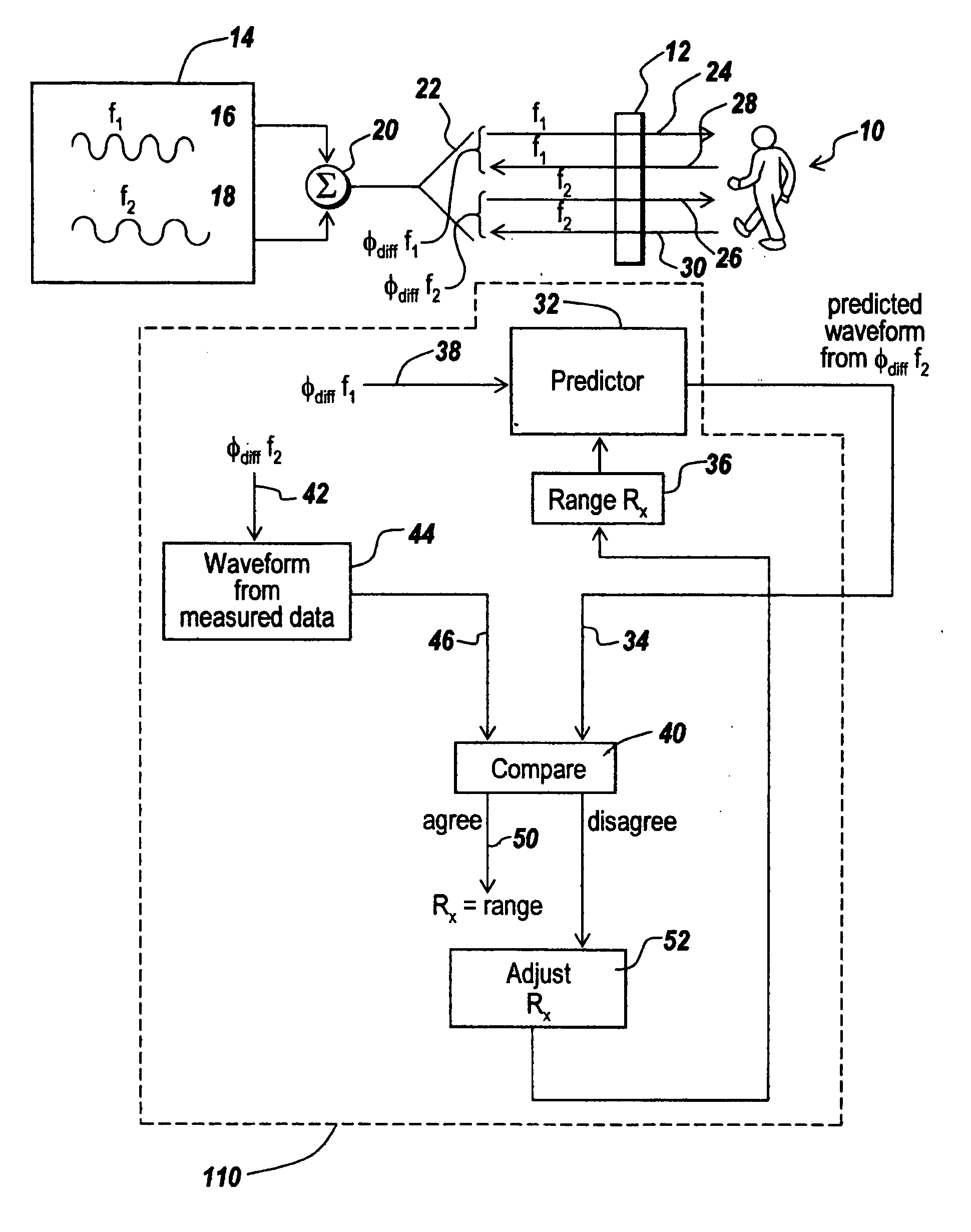
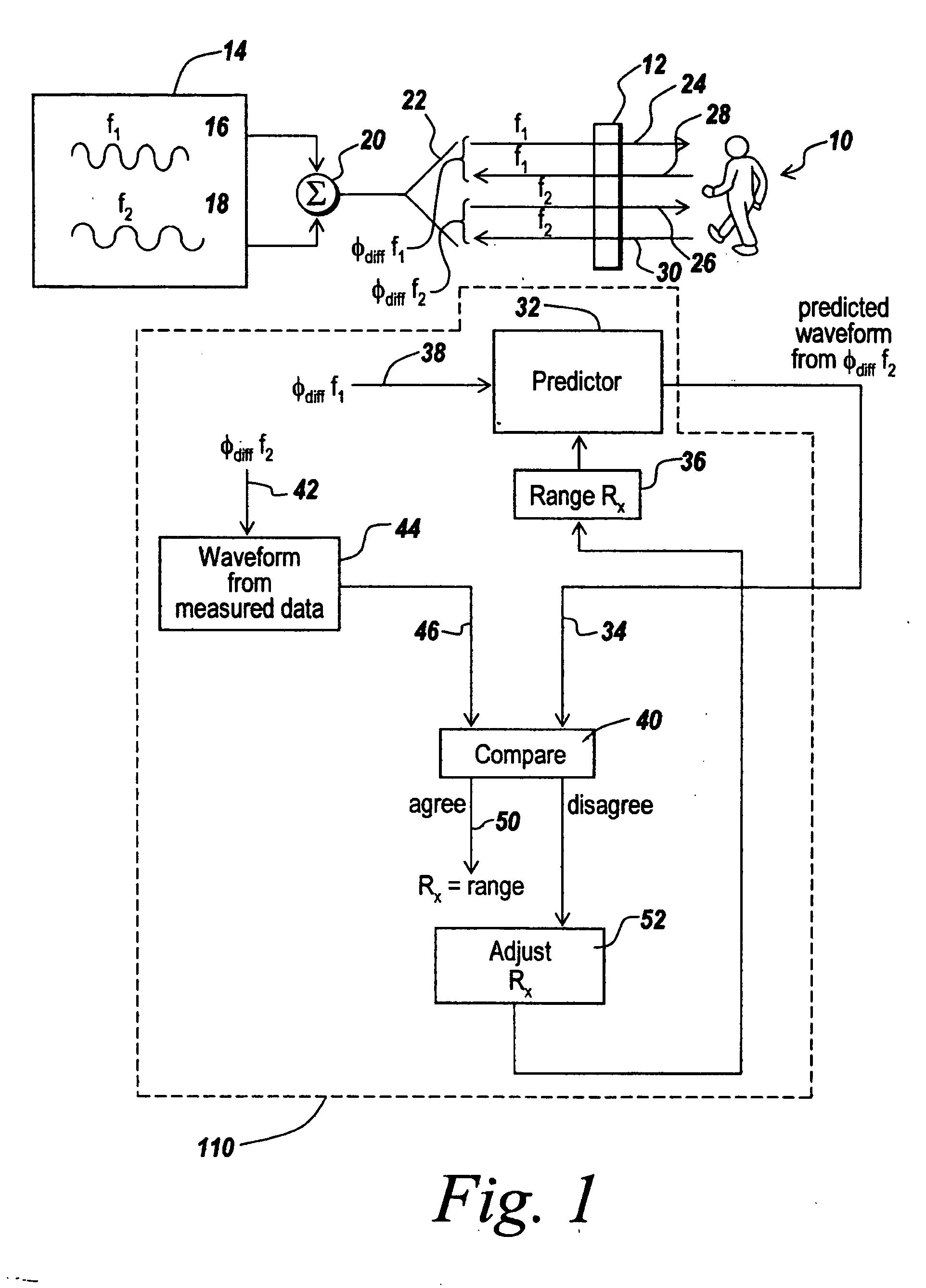
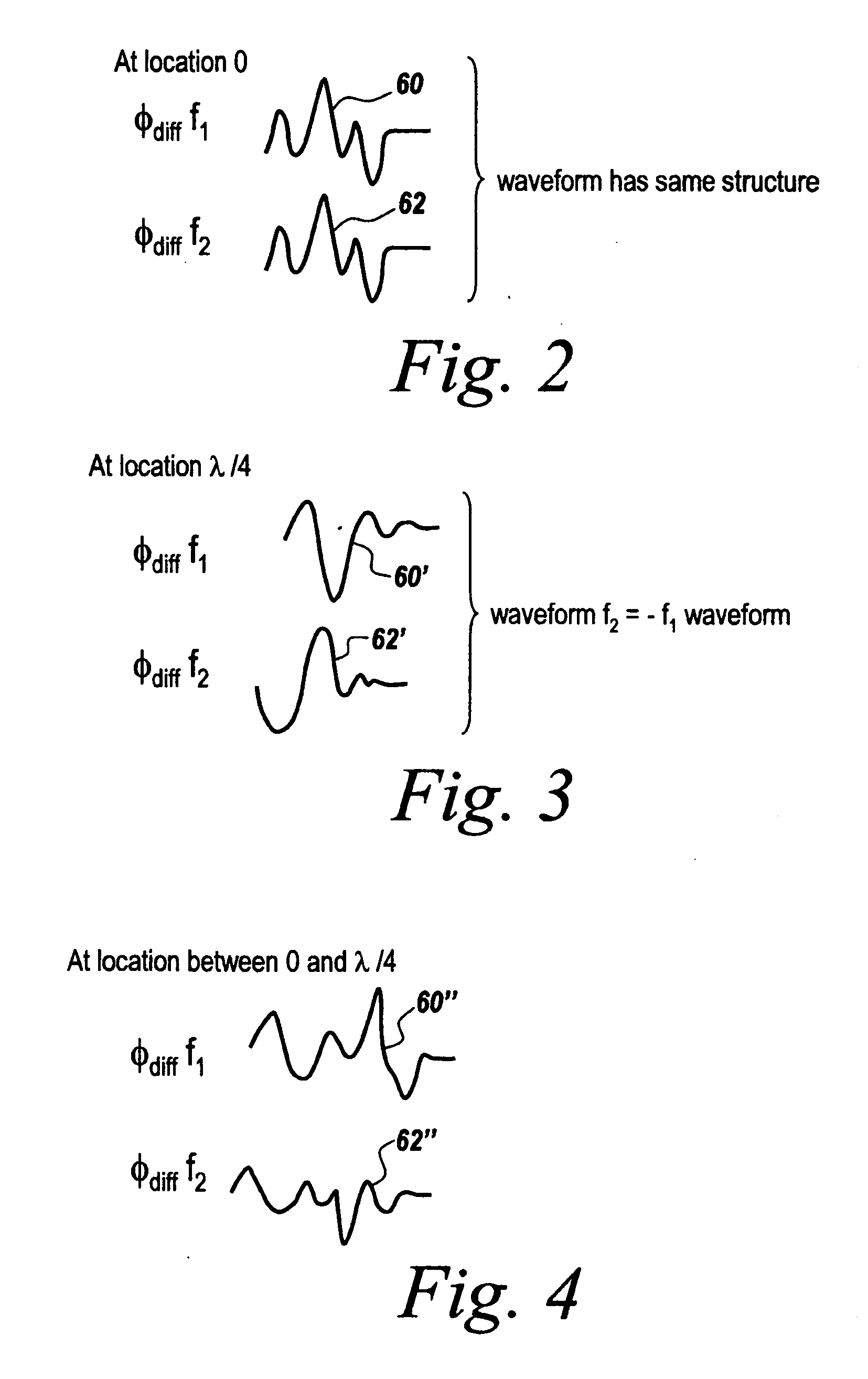
[0043] To describe the operation of the multi-tone CW radar used in the subject invention, it was found that for an object exhibiting constant motion or velocity the phase shift between the two waveforms representing the phase difference between transmitted and returned waves for the two tones or frequencies is directly related to range. This is because comparing waveforms corresponding to the phase difference between the outgoing and incoming waves at the two frequencies results in a relationship between the phase shift between the two waveforms and range. For instance, at zero range there is no difference in phase between the two waveforms. At a range equal to λ / 4 one has a 180° phase shift between the two waveforms. In between, for constant motion objects there is a linear relationship between phase shift and range such that by measuring phase shift between the two waveforms one can deduce range. Here λ is the wavelength associated with the difference in f1 an...


PUM


Abstract

Lower resolution and clutter-prone two-tone CW radars can have the displayed images dramatically improved by three techniques involved in the subject invention. The three techniques involved are the stepping of each of the multiple radars for readings at multiple frequencies, weighting the results to compensate for wall-induced distortions and differential image processing. In one embodiment, weights for each frequency counteract the distortion produced by particular wall. For differential image processing, temporal snapshots of the images are subtracted one from the other such that the result is only due to moving objects, thus to provide a dramatic display of the presence and position of moving individuals behind a wall.

Description

RELATED APPLICATIONS [0001] This application is a continuation-in-part of U.S. Patent Application Serial No. PCT / US2004 / 036446 filed Nov. 2, 2004, entitled Dual Frequency Through-the-wall Motion Detection and Ranging Using Difference-Based Estimation Technique, which is a continuation-in-part of U.S. Patent Application Serial No. PCT / US2004 / 030116 filed Sep. 14, 2004, the contents of which are incorporated herein by reference.STATEMENT OF GOVERNMENT INTEREST [0002] The invention was made with United States Government support under Contract (Grant) No. N39998-97-C-5216. The United States Government has certain rights in this invention.FIELD OF THE INVENTION [0003] This invention relates to through-the-wall sensors and more particularly to the improvement on accuracy for those through-the-wall sensors using two-tone CW radars by frequency stepping the radars, weighting the results, and detecting motion through differential image formation techniques. BACKGROUND OF THE INVENTION [0004]...

Claims


Application Information

Patent Timeline
IPC IPC(8): G01S13/62
CPCG01S13/32G01S13/56G01S13/89G01S13/888G01S13/87
Inventor ZEMANY, PAUL D.
Owner BAE SYST INFORMATION & ELECTRONICS SYST INTERGRATION INC
Why Eureka
Try Eureka