Covert Security Coating

a technology of optical coating and covert security, applied in the field of thin film optical coating, can solve the problems of compromising the ability of the average person to authenticate a security hologram conclusively, no countermeasure, taken alone, and difficult identification and recollecting of respective images produced by such holograms for verification purposes

Active Publication Date: 2006-12-21
VIAVI SOLUTIONS INC
View PDF77 Cites 66 Cited by
  • Summary
  • Abstract
  • Description
  • Claims
  • Application Information

AI Technical Summary

Benefits of technology

[0026] Thus, it is an object of the invention to provide a security device having a dielectric layer forming a Fabry Perot cavity or within a dielectric stack of dielectric layers wherein the dielectric layer has varying thicknesses so as to form optical cavities exhibiting different colors as visible light is incident thereon; and wherein the visual effect of the different colors is not seen without magnification. In addition, these different regions each have their own color shift with viewing angle.

Problems solved by technology

Various ways to counteract these methods have been explored but none of the countermeasures, taken alone, has been found to be an effective deterrent.
A further problem with security holograms is that it is difficult for most people to identify and recollect the respective images produced by such holograms for verification purposes.
The ability of the average person to authenticate a security hologram conclusively is compromised by the complexity of its features and by confusion with decorative diffractive packaging.
Thus, most people tend to confirm the presence of such a security device rather than verifying the actual image.
Unfortunately, this added complexity does not confer added security because this complex imagery is hard to communicate and recollection of such imagery is difficult, if not impossible, to remember.

Method used


Image

  • Covert Security Coating
  • Covert Security Coating
  • Covert Security Coating

Examples


Embodiment Construction

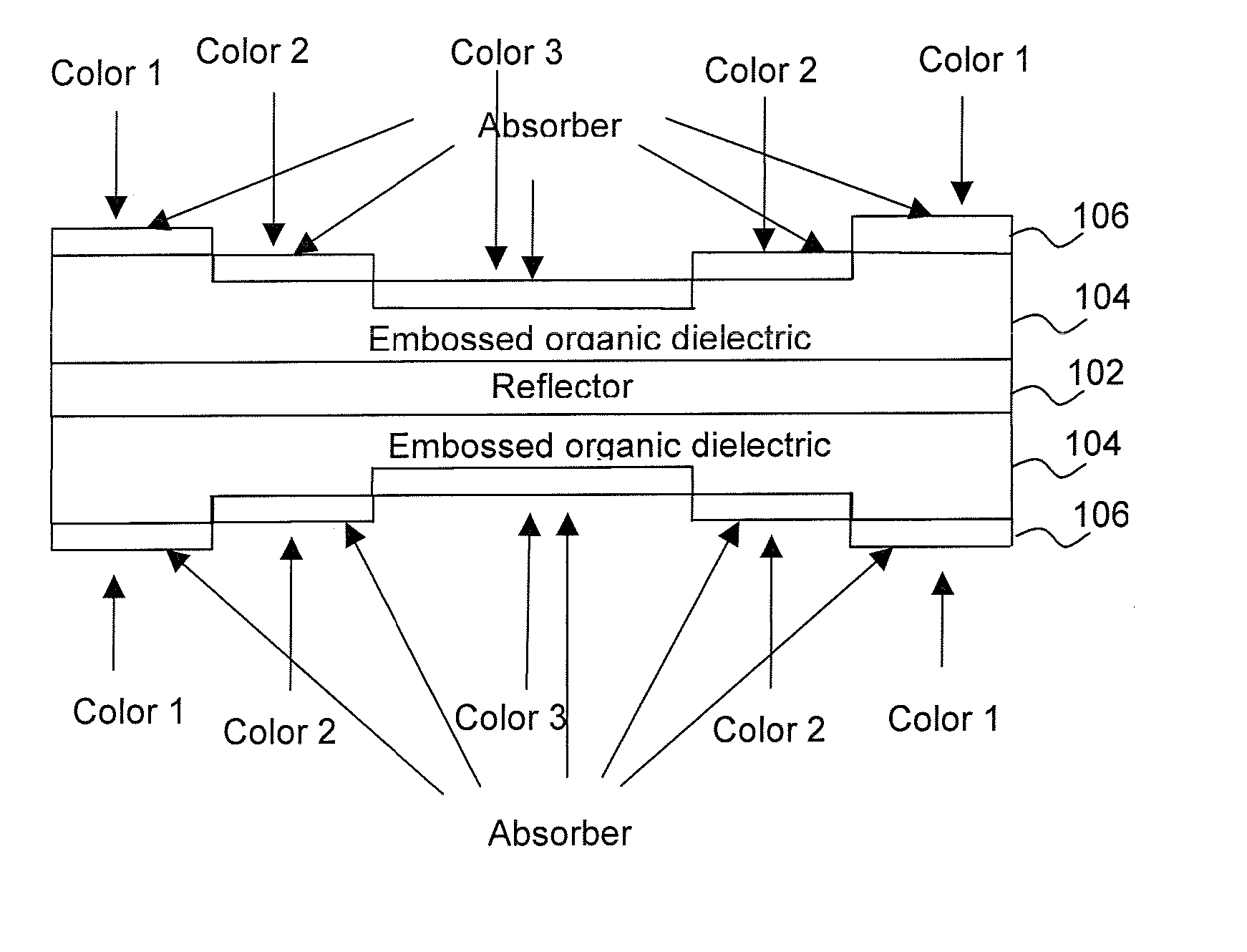
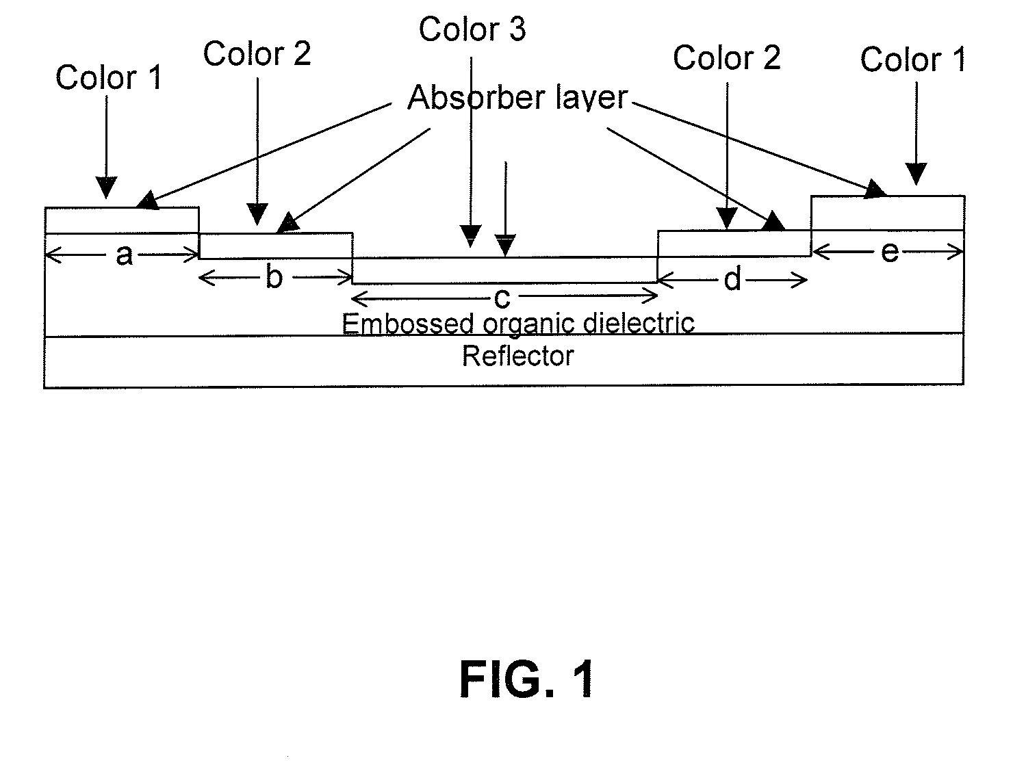
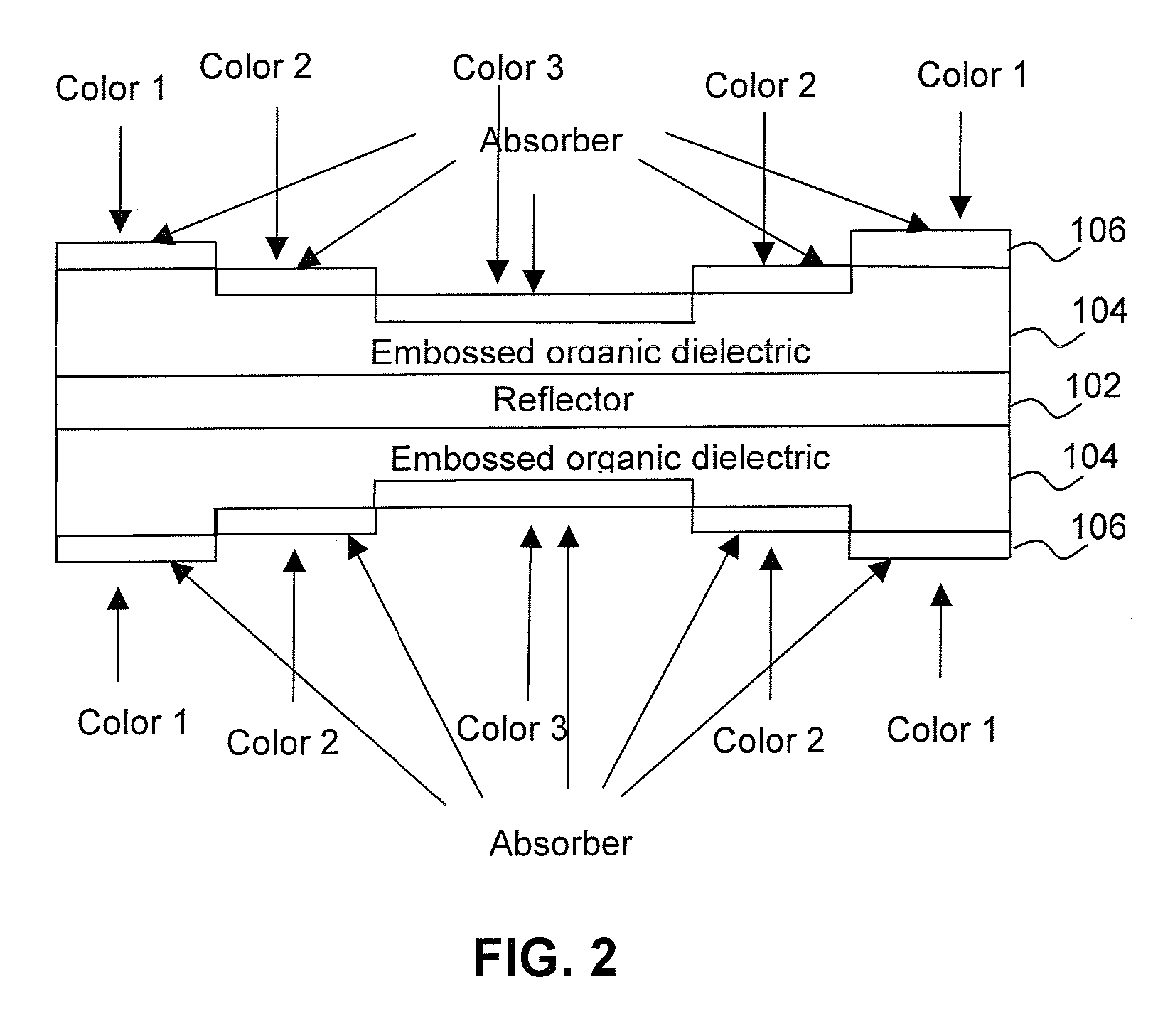
[0070] Turning now to FIG. 1, a portion of a sheet of foil 100 is shown in cross section, wherein the foil 100 includes a bottom reflector layer 102 having a uniform thickness; upon the reflector layer 102 is deposited on an organic dielectric layer 104 which is embossed so as to have a varying thickness and providing dielectric spacer regions differing in thickness. An absorber layer 106 is deposited to a uniform thickness over the variable thickness organic dielectric layer 104. In a preferred embodiment, the size of the adjacent regions (a) through (e) should be less than the size of a pixel or element that can be seen by the human eye. However, the invention does not require all adjacent steps or different thickness regions to be less than the size a human eye can see, however there must at least be one such element or region to provide the covert desired feature. For example, any element (a) through (e) could be sized to be small enough so that magnification is required to see ...


PUM


Abstract

A multilayer thin film filter is disclosed an organic dielectric layer serving as a spacer layer in a Fabry-Perot structure. The dielectric has embossed regions of varying thicknesses wherein the thickness within a region is substantially uniform. Each different region of a different thickness produces a different color (shift). The size of one of the embossed adjacent regions is such that the color of said one region is uniform and cannot be seen by a human eye as different in color from the uniform color of an adjacent region thereto, and wherein the color within a region can be seen with magnification of at least 10:1. This serves as a covert color coding system useful as a security device.

Description

CROSS-REFERENCE TO RELATED APPLICATIONS [0001] The present invention claims priority from U.S. Patent Application No. 60 / 691,499 filed Jun. 17, 2005, which is incorporated herein by reference for all purposes.FIELD OF THE INVENTION [0002] This invention relates generally to thin film optical coatings for use in producing security articles and to the production of diffractive surfaces such as holograms or gratings having color shifting or optically variable backgrounds which can be used as security articles in a variety of applications. More particularly this invention relates to the field of coating and or stamping a dielectric substrate to provide a grating or hologram preferably within a vacuum roll coating chamber while in a vacuum to produce a Chromagram™ type of device or to produce a base device on which to fabricate a Chromagram™ type of device. The invention also relates to the manufacture of a covert optical device having a dielectric layer of varying thickness. By way of e...

Claims


Application Information

Patent Timeline
Patent Type & Authority Applications(United States)
IPC IPC(8): G03H1/00
CPCB41M3/003B42D25/328B42D2035/24G02B5/284G02B5/287G03H1/0011G03H1/02G03H1/0236G03H1/0244G03H1/0256G03H1/028G03H2001/188G03H2225/31G03H2270/24B41M3/14H01P1/20G03H1/04B42D25/425
Inventor PHILLIPS, ROGER W.BIE, ROY
Owner VIAVI SOLUTIONS INC
Why Eureka
Try Eureka