Incident light redistribution to compensate for radial gradient in detector

a detector and incident light technology, applied in the direction of optical radiation measurement, luminescent dosimeter, instruments, etc., can solve the problem of not fully achieving the goal

Active Publication Date: 2006-12-21
BIO RAD LAB INC
View PDF3 Cites 0 Cited by
  • Summary
  • Abstract
  • Description
  • Claims
  • Application Information

AI Technical Summary

Problems solved by technology

Although uniform light distribution across the well array is the goal, this goal is not fully achieved because the line at the angle betwe...

Method used


Image

  • Incident light redistribution to compensate for radial gradient in detector
  • Incident light redistribution to compensate for radial gradient in detector
  • Incident light redistribution to compensate for radial gradient in detector

Examples


Embodiment Construction

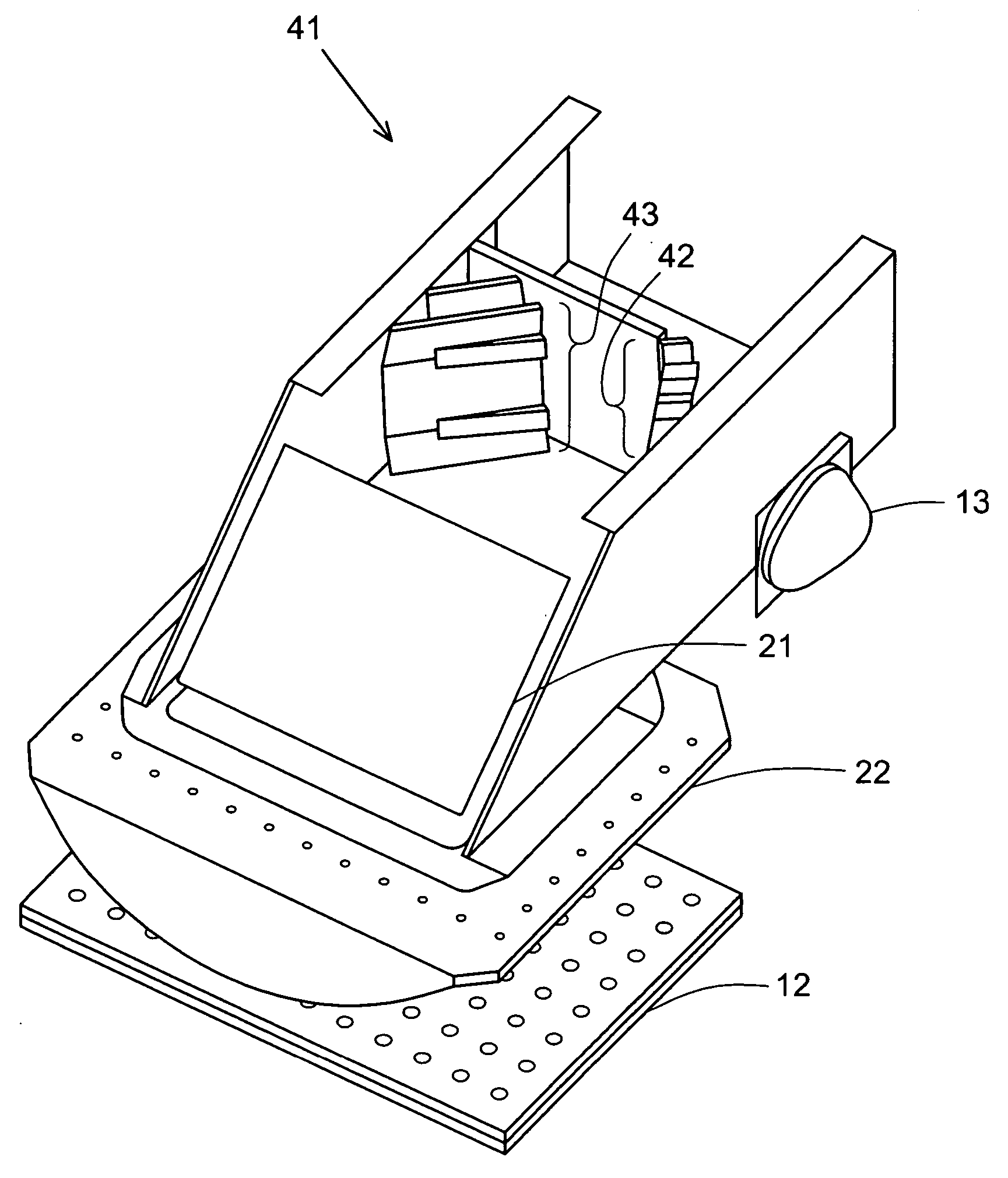
[0018] While the invention is susceptible to certain variations and a range of embodiments, the defining features of the invention are best understood by a detailed study of a single embodiment. One such embodiment is shown in FIGS. 3, 4, and 5 and described below.

[0019] The various mirrors that are the subject of this invention are segmented mirrors, and each segment is itself a planar mirror as distinguished from mirrors with curved surfaces. The various segments are oriented at angles relative to each other and adjacent segments share a common boundary or seam line, in the manner of facets in a faceted mirror. The term “linearly joined” is used herein to denote mirror segments that are joined sequentially side-to-side to form a chain. The term “segment” when used to describe a portion of a mirror refers to a single planar facet or section.

[0020] The terms “comprise,”“comprises,” and “comprising,” unless otherwise indicated, are used herein to denote the inclusion of the element...


PUM


Abstract

Nonuniformities in the efficiency of detection of individual fluorescing reaction mixtures in a well plate with a two-dimensional array well array are corrected. The nonuniformities arise both from the stimulation pattern and the detection pattern, and are corrected by adding additional segments to a pair of segmented mirrors. The additional segments are oriented to direct light to the outermost reaches (i.e., the four corners) of the array and thereby produce a stimulation pattern that has a greater intensity in the outermost regions. This compensates for a radial decline in the efficiency of the detector in detecting the emissions from the well plate, the radial decline being an artifact of systems that utilize CCDs or similar components as detectors.

Description

CROSS-REFERENCE TO RELATED APPLICATION [0001] This application claims benefit from U.S. Provisional Patent Application No. 60 / 681,204, filed May 13, 2005, the contents of which are incorporated herein by reference in their entirety.BACKGROUND OF THE INVENTION [0002] 1. Field of the Invention [0003] This invention relates to the generation and detection of electromagnetic emissions in a multitude of samples retained in individual wells of multi-well plates or two-dimensional sample arrays in general. This invention is of particular interest in the performance of the polymerase chain reaction (PCR) with real-time detection, i.e., PCR processes in which the amounts of nucleic acid in individual reaction wells are quantitated as the PCR reaction is progressing. The invention has general applicability however to any system that simultaneously detects emission signals from a multitude of wells, receptacles, or sample spots in a two-dimensional rectangular array. [0004] 2. Description of t...

Claims


Application Information

Patent Timeline
IPC IPC(8): G02B23/00
CPCG02B27/0977G02B27/0927
Inventor PATT, PAUL J.ARCINIEGAS, GERMANCEREMONY, JEFFRY
Owner BIO RAD LAB INC
Why Eureka
Try Eureka