
Mapping radio-frequency noise in an ultra-wideband communication system

a radio frequency noise and ultra-wideband communication technology, applied in the field of wireless communication systems, can solve the problems of affecting the reliability of data links, the amount of data sent on both wide and local communication systems is mushrooming, and the bandwidth available in the traditional communication band is quickly exceeded

Inactive Publication Date: 2006-12-21
INTELLECTUAL VENTURES HOLDING 81 LLC
View PDF42 Cites 25 Cited by
  • Summary
  • Abstract
  • Description
  • Claims
  • Application Information

AI Technical Summary

Benefits of technology

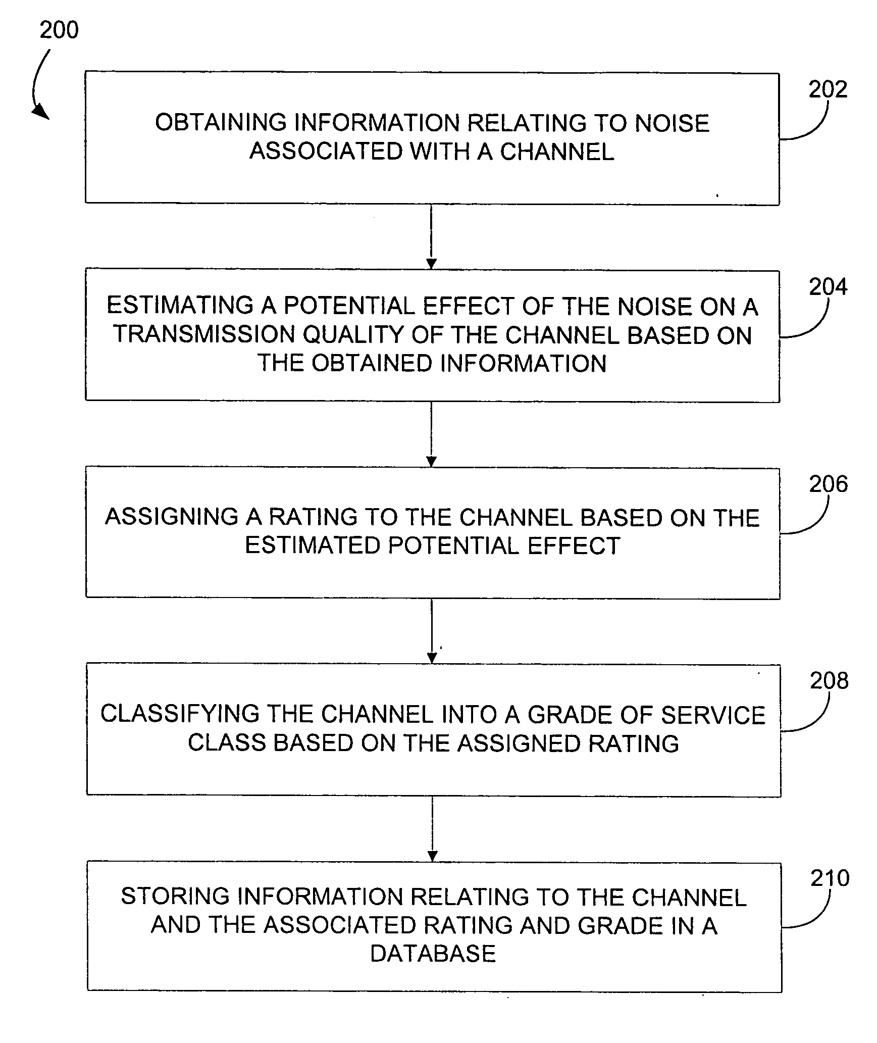
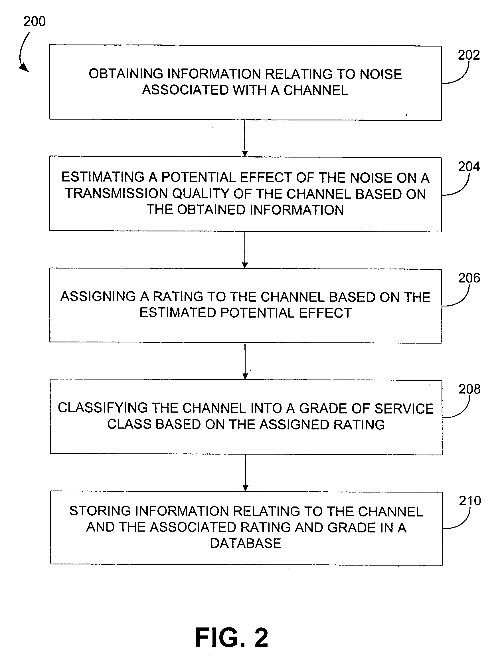
"The present invention provides a method for mapping the RF noise floor in ultra-wideband communication systems. This helps to identify channels with low RF noise and avoid them for high data-rate transmissions, increasing the quality and reliability of the communication. The method involves assigning time bins to communication channels and averaging RF amplitude data from selected time bins to obtain an average RF amplitude in each channel. The channels are then ranked based on the characteristics of the RF noise, and the rate of change in the RF amplitude average across multiple channels indicates whether the RF noise is periodic or substantially constant, or if it is recurring."

Problems solved by technology

The amount of data being sent on both wide and local communication systems is mushrooming, and may quickly exceed the bandwidth available in the traditional communication bands.
Currently, with the vast amount of data being sent across local and wide area communication systems, radio frequency (RF) “noise” is impacting the reliability of data links.
Similarly, noise might be generated from a laptop computer, or other devices that can resonate, creating additional RF noise that can impact UWB communications.

Method used


Image

  • Mapping radio-frequency noise in an ultra-wideband communication system
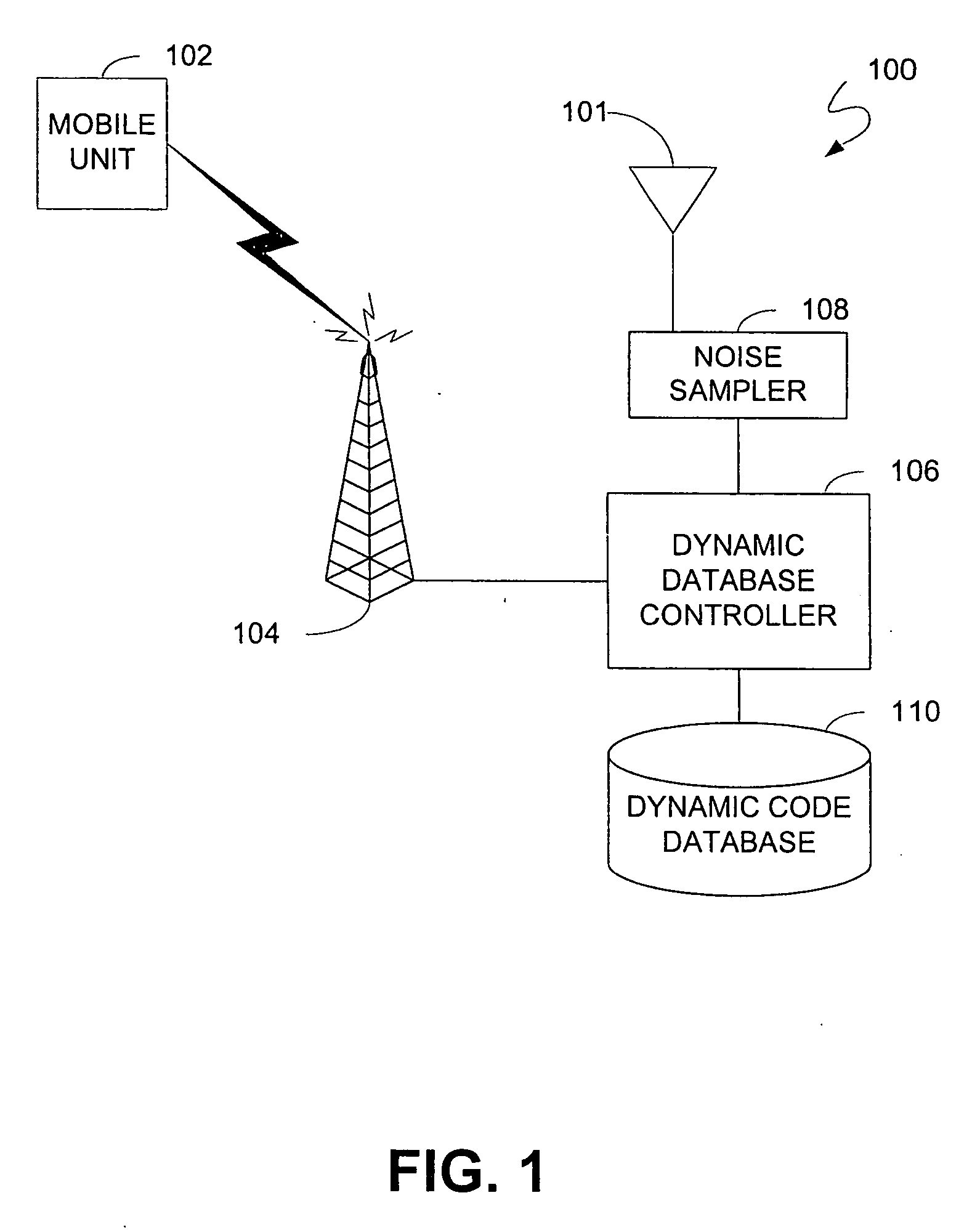
  • Mapping radio-frequency noise in an ultra-wideband communication system
  • Mapping radio-frequency noise in an ultra-wideband communication system

Examples


Embodiment Construction

[0029] In the following paragraphs, the present invention will be described in detail by way of example with reference to the attached figures. Throughout this description, the preferred embodiment and examples shown should be considered as exemplars, rather than as limitations on the present invention. As used herein, “the present invention” and “the invention” refer to any one of the embodiments of the invention described herein.

[0030]“Ultra-wideband” (UWB) is also known as “carrier-free”, “baseband” or “impulse” technology. The basic concept is to develop, transmit and receive an extremely short duration burst of radio-frequency (RF) energy—typically a few tens of picoseconds (trillionths of a second) to a few hundred nanoseconds (billionths of a second) in duration. These bursts represent from one to only a few cycles of an RF carrier wave. The resultant waveforms are extremely broadband, so much so that it is often difficult to determine an actual RF center frequency—thus, the...


PUM


Abstract

A system and method for mapping. radio-frequency (RF) noise, and estimating channel quality in a multi-channel ultra-wideband communication system is provided. One method includes placing a plurality of time bins within a plurality of time frames and assigning a plurality of UWB communication channels comprising selected time bins. RF noise amplitude data is then sampled from selected time bins. The sampled RF noise amplitude data from the time bins is then averaged, thereby obtaining an average RF noise amplitude in each of the plurality of channels. The RF noise amplitude indicates the amount of RF noise present in a channel. The channels may then be ranked based on the characteristics of the RF noise.

Description

[0001] This application claims priority under 35 U.S.C. § 120 as a continuation of U.S. patent application Ser. No. 09 / 802,603, filed Mar. 9, 2001, entitled “Mapping Radio-Frequency Noise in an Ultra-Wideband Communication System”, which claims priority from U.S. provisional application Ser. No. 60 / 255,469, filed on Dec. 14, 2000, entitled “Ultra-wideband Communication System and Method”, which is incorporated herein by reference in its entirety.FIELD OF THE INVENTION [0002] The field of the present invention generally relates to wireless communication systems. More particularly, the invention concerns a method to map radio frequency noise in an ultra-wideband communication system. BACKGROUND OF THE INVENTION [0003] Wireless communication systems are changing the way people work, entertain themselves, and communicate with each other. For example, the wide acceptance of mobile devices, such as the portable phone, has enabled great mobility while enabling easy voice and data communica...

Claims


Application Information

Patent Timeline
Patent Type & Authority Applications(United States)
IPC IPC(8): H04B1/00H04L27/06G01S13/87H04B1/10H04B17/00H04L1/08H04L1/18H04L1/20H04W72/54
CPCG01S13/878H04B1/1027H04B1/7174H04B1/7176H04L1/08H04B17/309H04L1/1829H04L5/023H04W72/08H04L1/203H04L1/1816H04W72/54
Inventor SANTHOFF, JOHN H.ARRIETA, RODOLFO T.MILLER, CHARLES E.
Owner INTELLECTUAL VENTURES HOLDING 81 LLC
Learn More