Core drill assembly with the ability to control angle of drilling

a technology of angle regulator and core drill, which is applied in the direction of drilling/boring measurement devices, portable drilling machines, manufacturing tools, etc., can solve the problems of difficult to fix the angle at which the user would like to drill, the angle regulator of a contemporary core drill assembly is limited in and the selection of drilling angles that the core drill assembly can drill, etc., to achieve the effect of secure adjustmen

Inactive Publication Date: 2006-12-21
CABEL
View PDF14 Cites 15 Cited by
  • Summary
  • Abstract
  • Description
  • Claims
  • Application Information

AI Technical Summary

Benefits of technology

[0015] The core drill assembly is operative to angularly position the stand to preselected angles between 60 and 120 degrees. The range of angles is defined between the stand longitudinal axis and the base axis with respect to an angular direction away from the surface plane and towards the base axis. The embodiment has the advantage of selecting from a range of angles to drill both away from and towards the base of the core drill assembly as well as perpendicular to the base.
[0016] The core drill assembly having a drill motor defining a drill longitudinal axis. The drill longitudinal axis is parallel to the stand longitudinal axis. The embodiment of the invention has the advantage of the drilling angle equal to the angle between the stand longitudinal axis and the base axis.
[0017] The core drill assembly having two disc structures. The two disc structures having ribbed boundaries. The two disc structures are disposed between the base and the stand holder. The embodiment has the advantage of securely adjusting between preselected angles of drilling.
[0018] The core drill assembly having two disc structures with ribbed boundaries that interlock and engage the stand holder and the base at a preselected angle. This embodiment of the invention has the advantage of securing the angle of drilling of the core drill assembly.

Problems solved by technology

While such a core drill assembly is useful for drilling surfaces at a perpendicular angle with respect to the base, the traditional core drill assembly cannot drill at any other angle but the perpendicular.
This presents a problem for those users who desire to bore or drill through a surface at an angle not perpendicular to the base of the device.
Despite the addition of an angle regulator to the core drill assembly, there are problems when drilling at an angle.
The angle regulator includes a complicated process that requires the user to set the angle of the core drill assembly after pulling out of the axis of rotation.
This process makes it very difficult to fix the angle at which the user would like to drill.
Additionally, the angle regulator of a contemporary core drill assembly is limited in the selection of drilling angles.
The diameter of the axis of rotation is too small, preventing the spline from being divided more systematically and limiting the selection of angles that the core drill assembly can drill.
The gap can be dangerous because it could cause the drill to shake during the boring process and break away from the original rotation angle or significantly pose a risk to the safety of the user or others in close proximity to the drill.
Besides the problems discussed above, the angle regulator is not capable of setting the drilling angle at an angle greater than the perpendicular or 90 degrees.
In other words, the drill is not capable of drilling towards the base at an angle.

Method used


Image

  • Core drill assembly with the ability to control angle of drilling
  • Core drill assembly with the ability to control angle of drilling
  • Core drill assembly with the ability to control angle of drilling

Examples


Embodiment Construction

[0029] The particulars shown herein are by way of example and for purposes of illustrative discussion of the embodiments of the present invention only and are presented in the cause of providing what is believed to be the most useful and readily understood description of the principles and conceptual aspects of the present invention. In this regard, no attempt is made to show structural details of the present invention in more detail than is necessary for the fundamental understanding of the present invention, the description taken with the drawings making apparent to those skilled in the art how the several forms of the present invention may be embodied in practice.

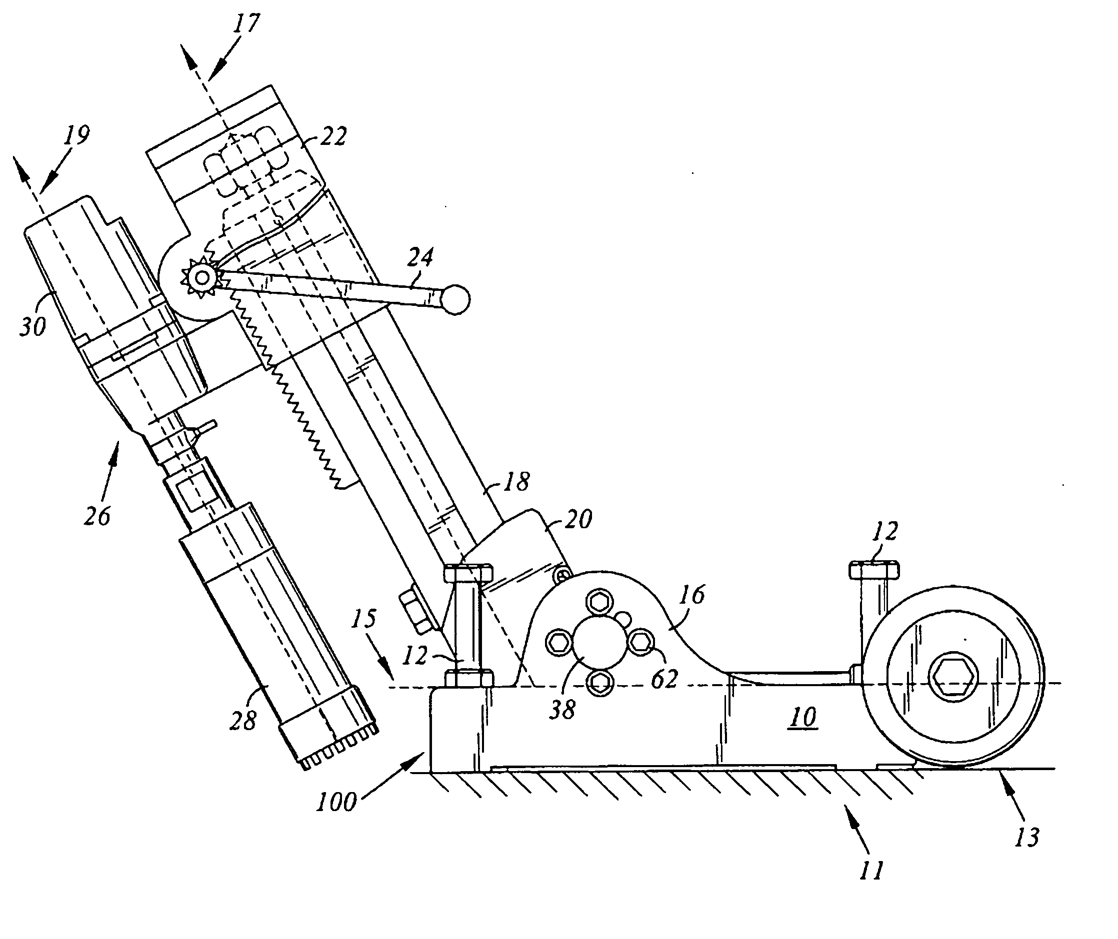
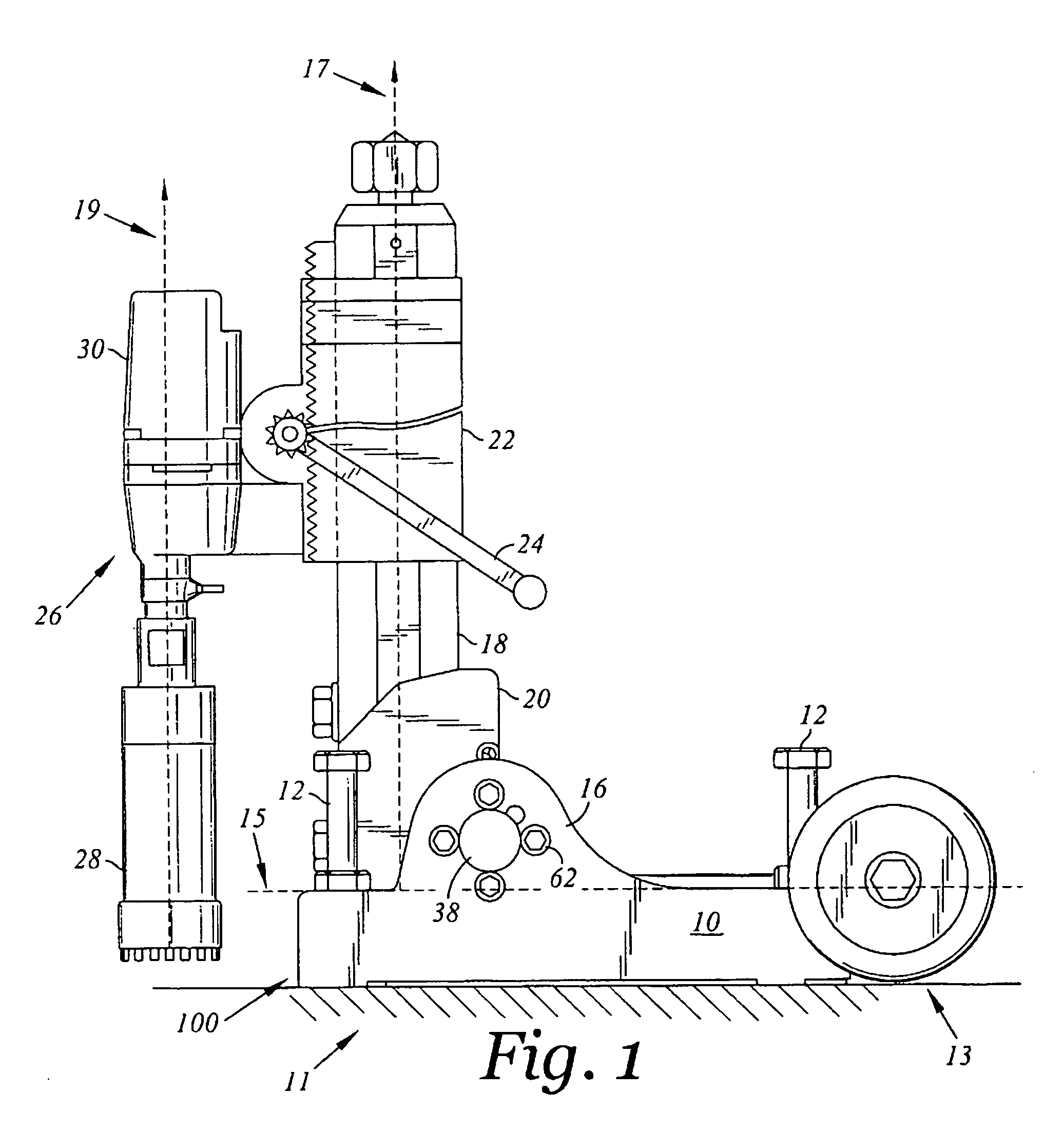
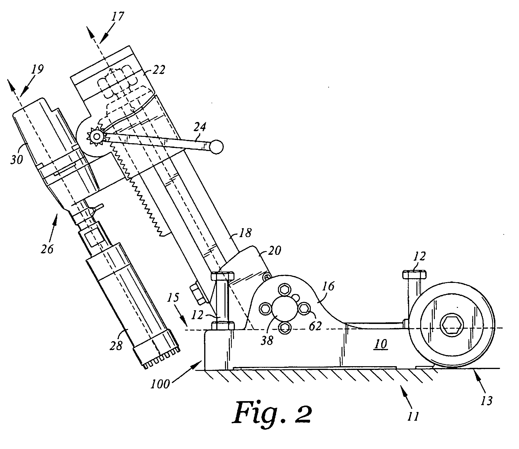
[0030] According to the embodiment as shown a core drill assembly 100 for use on a surface 11. The surface 11 defining a surface plane 13. The core drill assembly 100 comprising a base 10 configured to be deployable on the surface 11. The base 10 having opposing first and second ends with a base axis 15 extending from t...


PUM

PropertyMeasurementUnit
angleaaaaaaaaaa
anglesaaaaaaaaaa
anglesaaaaaaaaaa

Abstract

A core drill assembly provided for drilling on a surface at select angles capable of drilling both away from and towards the base. The surface that the core drill assembly is deployed upon defines a surface plane. The core drill assembly comprises a base deployable upon a surface. The base having first and second opposing ends and a base axis extending from the first end of the base to the second end parallel to the surface plane. The core drill assembly including a stand defining a stand longitudinal axis intersecting the base axis. The stand is pivotally connected to the base and angularly positionable between acute and obtuse angles defined between the stand longitudinal axis and the base axis with respect to an angular direction away from the surface plane towards the base axis. A drill motor including drill bit is coupled to the stand.

Description

CROSS-REFERENCE TO RELATED APPLICATIONS [0001] This application claims benefit under 35 U.S.C. §119 from Korean Patent Application No. 10-2005-0052454, entitled ELECTRIC CORE DRILL MACHINE, filed on Jun. 17, 2005, the entire content of which is incorporated herein by reference. STATEMENT RE: FEDERALLY SPONSORED RESEARCH / DEVELOPMENT [0002] Not Applicable BACKGROUND OF THE INVENTION [0003] The present invention relates to a core drill assembly used to bore through the surface it is deployed upon. More particularly, the invention is directed to a device useful for drilling upon a surface at angles adjustable to allow the drill to bore towards, away, or perpendicular from the base of the device. [0004] The traditional core drill assembly is a mechanical device used as a tool to bore through certain materials. The core drill assembly generally consists of a base, the base being fixed to the surface to be bored by bolts. The core drill assembly includes a stand perpendicular to the base, ...

Claims


Application Information

Patent Timeline
Patent Type & Authority Applications(United States)
IPC IPC(8): B23B45/14
CPCY10T408/564B25H1/0042B23B49/00B23B47/00
Inventor PARK, NO-HWAN
Owner CABEL
Why Eureka
Try Eureka