Mounting structure for air cleaner

a technology for mounting structures and air cleaners, which is applied in the direction of rod connections, filtration separation, and separation processes, etc., can solve the problems of degrading the appearance and affecting the operation of the air cleaner itself. , to achieve the effect of easy release and good operation

Inactive Publication Date: 2006-12-28
KAWASAKI HEAVY IND LTD
View PDF10 Cites 15 Cited by
  • Summary
  • Abstract
  • Description
  • Claims
  • Application Information

AI Technical Summary

Benefits of technology

[0015] According to this feature, when the slider is to be moved by sliding, the slider can be held at selected position by the stopper function of the resistance member and, therefore, a good operationality can be appreciated. Specifically, when the position of the slider is so determined that when the air cleaner cover is coupled with the air cleaner casing, the slider can straddle over the air cleaner casing or both the cover...

Problems solved by technology

It has, however, been found that although the use of the thumbscrews is effective to firmly secure the air cleaner cover to the air cleaner casing, removal of the thumbscrews during the replacement of the used cleaner element and/or servicing of the air clea...

Method used


Image

  • Mounting structure for air cleaner
  • Mounting structure for air cleaner
  • Mounting structure for air cleaner

Examples


Embodiment Construction

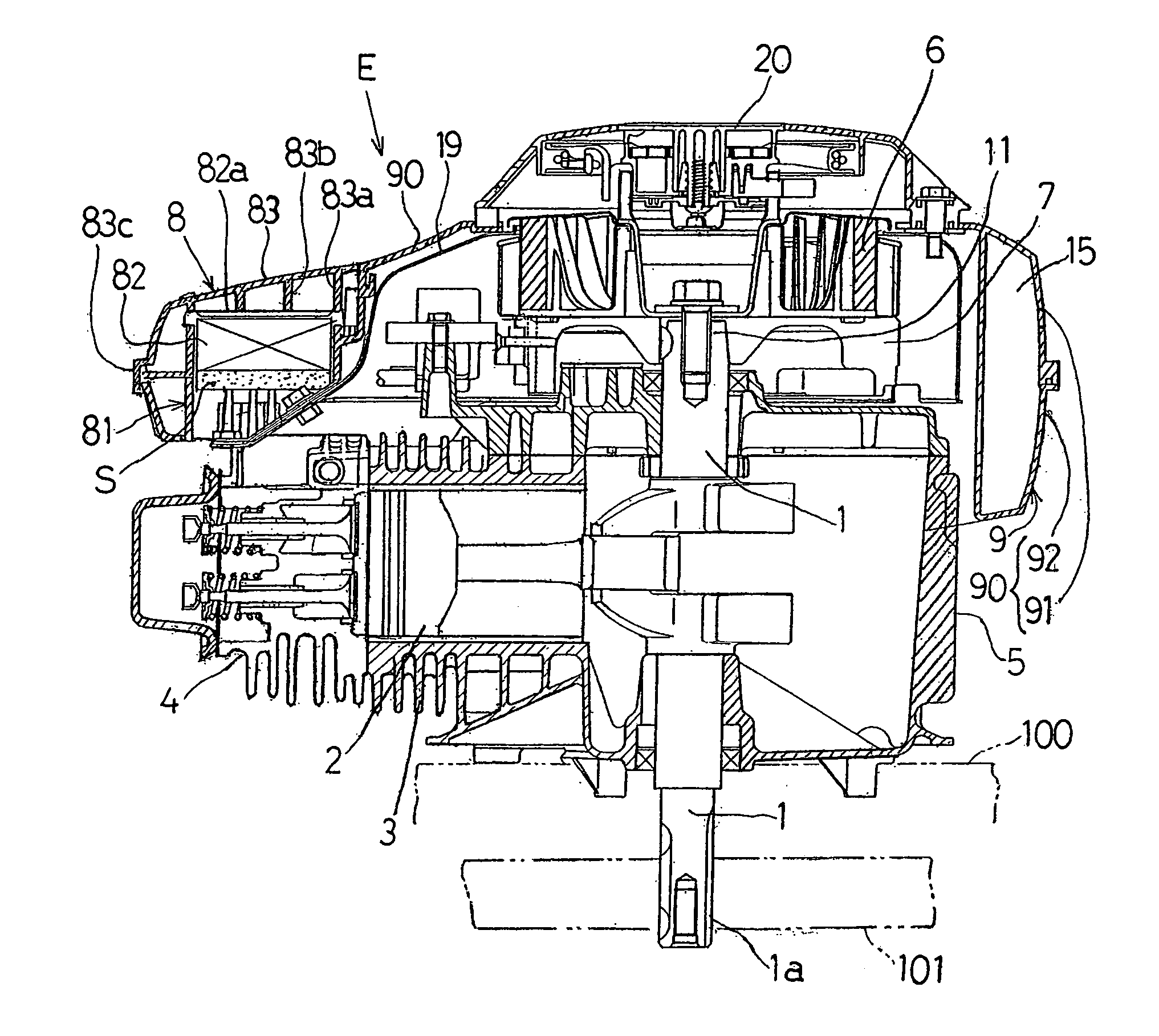
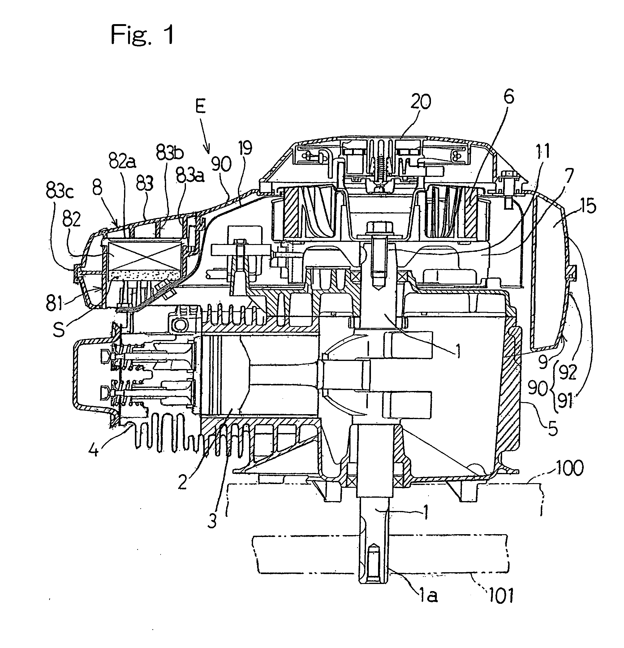
[0030] Reference will now be made to the accompanying drawing for the detailed description of a preferred embodiment of the present invention. As shown in FIG. 1, there is shown a combustion engine E of a vertical shaft type including a crankcase 5 and a crankshaft 1 extending vertically through the crankcase 5. The Engine E also includes a horizontally laid cylinder block 3 formed integrally with the crankcase 5 and having a cylinder bore defined therein. A piston 2 is horizontally arranged within the cylinder bore of the cylinder block 3 for connection with the crankshaft 1 so that the piston 2 can reciprocate horizontally within the cylinder bore of the cylinder block 3. A cylinder head 4 is secured to an open end of the cylinder block 3.

[0031] The crankshaft 1 has an upper end 11 protruding upwardly outwardly from the crankcase 5. A cooling fan 6 and a flywheel 7 are mounted on the upper end 11. The crankshaft 1 also has a lower end 1a protruding downwardly outwardly from the c...


PUM

PropertyMeasurementUnit
Forceaaaaaaaaaa
Electrical resistanceaaaaaaaaaa

Abstract

A mounting structure for an air cleaner on a combustion engine according to the present invention includes an engine cover (9) for covering at least a portion of the combustion engine (E). The cover (9) includes an air cleaner casing (81) having an opening and an air cleaner cover (83) for covering the opening of the air cleaner casing (81). Flanges (81f, 83f) are formed in respective joint portions of the air cleaner casing (81) and the air cleaner cover (83). The mounting structure also includes a slider (10) movable between a disengagement position and an engagement position in a direction parallel to the joint portions. This slider (10) when moved to the engagement position connects the flanges (81f, 83f) of the air cleaner casing (81) and cover (83), but when moved to the disengagement position the slider (10) enables the cover (83) to be released from the casing (81).

Description

BACKGROUND OF THE INVENTION [0001] 1. Field of the Invention [0002] The present invention generally relates to a mounting structure for an air cleaner on a combustion engine of a vertical shaft type that is used as a drive source for a working machine such as a lawn mower. [0003] 2. Description of the Prior Art [0004] For a drive source used for driving a lawn mower, a combustion engine of a vertical shaft type is generally employed such as disclosed in the Japanese Utility Model Registration No. 2542160. This type of internal combustion engine includes a crankcase and a crankshaft extending vertically from a bottom region of the crankcase. A top region of the combustion engine is covered by an engine cover. An air cleaner is mounted on the engine cover for purifying an intake air of the engine. [0005] The air cleaner includes an air cleaner casing formed integrally with the engine cover for accommodating a cleaner element and an air cleaner cover for closing an opening of the air c...

Claims


Application Information

Patent Timeline
IPC IPC(8): B01D50/00
CPCB01D46/0005B01D46/0039B01D46/10B01D46/521Y10T403/7045F02M35/0203F02M35/024F02M35/04Y10T403/7071F02B63/02
Inventor MIYAKE, HITOMIUEDA, YOSHITERUUEMURA, ICHIROYAMAKAWA, TETSUHIRO
Owner KAWASAKI HEAVY IND LTD
Why Eureka
Try Eureka