Cold storage tank unit and refrigeration cycle apparatus using the same

a technology of cold storage tank and refrigeration cycle, which is applied in the direction of domestic cooling apparatus, indirect heat exchangers, lighting and heating apparatus, etc., can solve the problems of deteriorating cooling capacity of the first and second evaporators, increasing material costs, etc., and achieves the effect of reducing size and cos

Inactive Publication Date: 2006-12-28
DENSO CORP
View PDF9 Cites 44 Cited by
  • Summary
  • Abstract
  • Description
  • Claims
  • Application Information

AI Technical Summary

Benefits of technology

[0010] In view of the foregoing problems, it is an object of the present invention to provide a cold storage tank uni...

Problems solved by technology

Hence, this hinders size reduction and causes to increase material cost because high-strength material needs to be selected.
When t...

Method used


Image

  • Cold storage tank unit and refrigeration cycle apparatus using the same
  • Cold storage tank unit and refrigeration cycle apparatus using the same
  • Cold storage tank unit and refrigeration cycle apparatus using the same

Examples


first embodiment

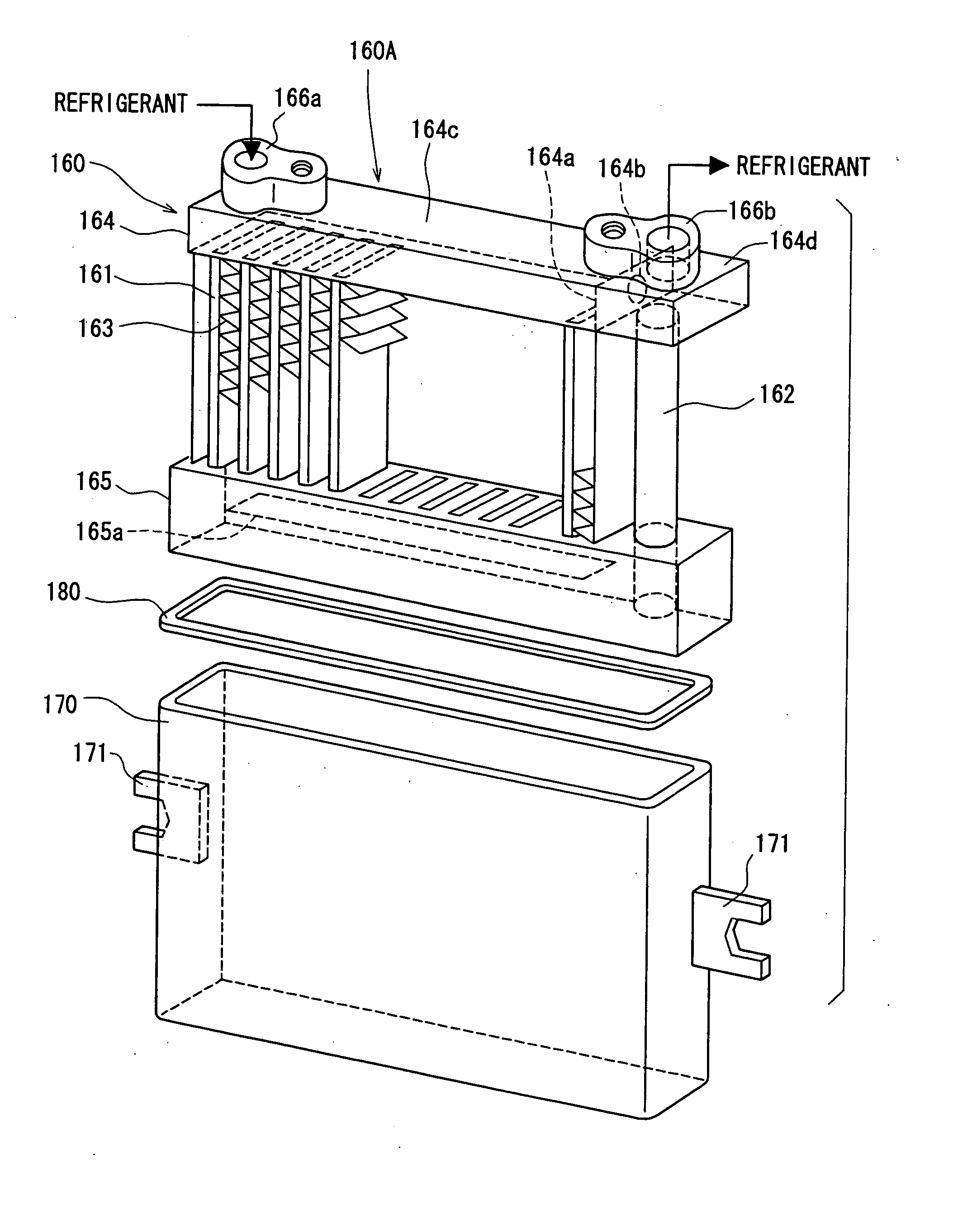
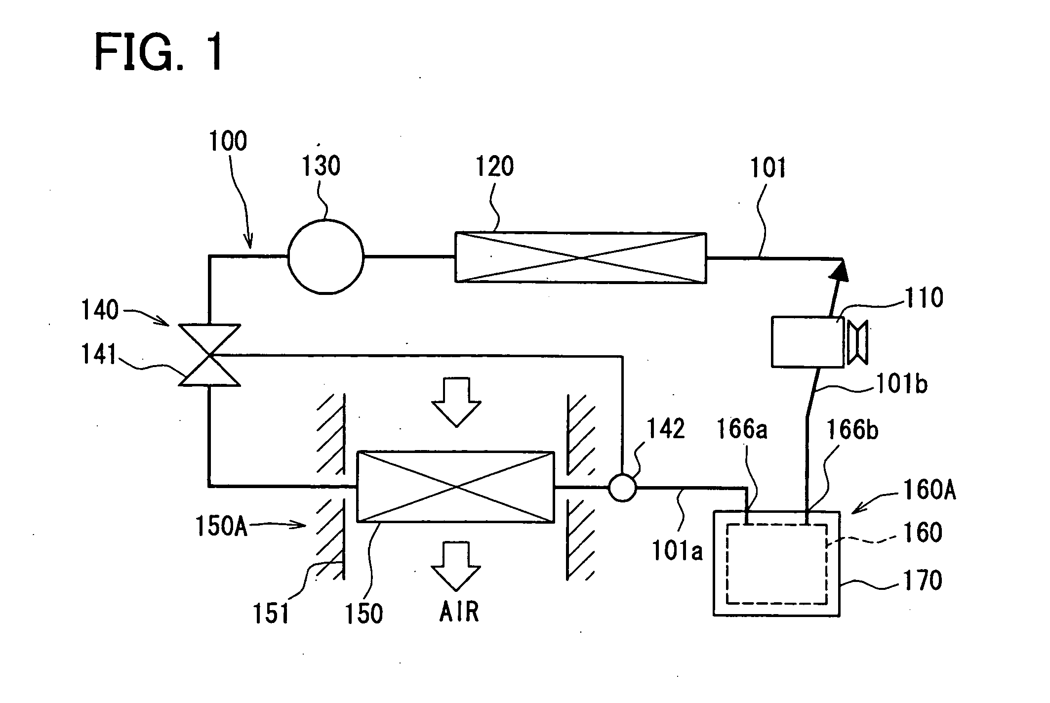
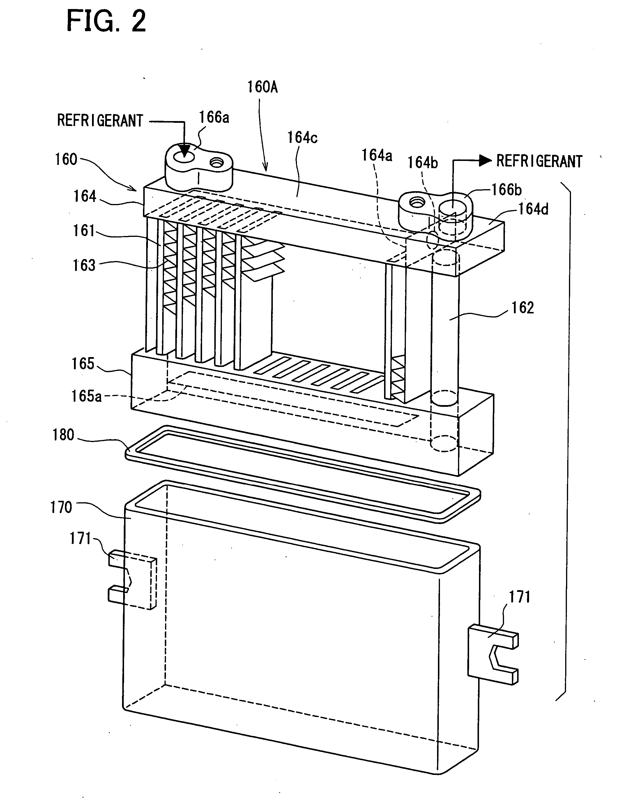
[0052] A refrigeration cycle apparatus 100 of a first embodiment is typically applied to a so-called idling stop vehicle in which an engine is stopped when the vehicle is shifted from a running state to a stopping state where the engine is idled, for example, when the vehicle waits at a traffic signal. The basic construction of the refrigeration cycle apparatus 100 will be described by the use of FIG. 1 to FIG. 3. Here, FIG. 1 is a schematic diagram showing the general construction of the refrigeration cycle apparatus 100. FIG. 2 is an exploded view in perspective showing a cold storage tank unit 160A. FIG. 3 is a cross-sectional view showing a return pipe 162 and a lower tank 165 of a cold storage heat exchanger 160.

[0053] The refrigeration cycle apparatus 100 transfers heat on a low temperature side to a high temperature side to use cold and heat for air conditioning. As shown in FIG. 1, the refrigeration cycle apparatus 100 is constructed with a cycle in which a usual compressor...

second embodiment

[0089] A second embodiment of the present invention will be shown in FIG. 4. The second embodiment is such that, as compared with the first embodiment, an internal heat exchanger 200 is added to a refrigeration cycle apparatus 100A.

[0090] The internal heat exchanger 200 exchanges heat between high-pressure side refrigerant between the condenser 120 and the expansion valve 140 (specifically, the liquid receiver tank 130 and the expansion valve 140) and low-pressure side refrigerant between the cold storage tank unit 160A and the compressor 110. The internal heat exchanger 200 is formed as a heat exchanger of, for example, a double pipe structure in which a low-pressure side pipe, through which the above-mentioned low-pressure side refrigerant flows, is arranged in a specified range (specified length) of a high-pressure side pipe, through which the above-mentioned high-pressure side refrigerant flows. That is, the high-pressure side refrigerant flows between the high-pressure side pi...

third embodiment

[0097] A third embodiment of the present invention is shown in FIG. 5. The third embodiment is such that, as compared with the first embodiment, a fixed throttle part 191 is arranged in parallel to the expansion valve 140 in a refrigeration cycle apparatus 100B.

[0098] Specifically, there is provided a bypass passage 210 bypassing the valve part 141 of the expansion valve 140 and this bypass passage 210 is provided with the fixed throttle part 211 having its opening fixed to a specified opening.

[0099] In the cold storage mode while the compressor 110 is operated, the expansion valve 140 opens the valve part 141 to a specified opening according to the refrigerant temperature (degree of superheat of refrigerant) of the temperature sensing part 142. However, in the cold release mode, there is a case where the compressor 110 is stopped to increase the low-pressure side pressure whereas the valve part 141 is gradually closed because the temperature sensing part 142 is cooled.

[0100] In ...


PUM


Abstract

A cold storage tank unit for a refrigeration cycle apparatus includes a cold storage heat exchanger having plural tubes and a pair of first and second tanks connected to longitudinal ends of the tubes, a cold storage material tank which accommodates at least the tubes of the cold storage heat exchanger, and a cold storage material filled in the cold storage material tank. The cold storage material is cold-stored by the refrigerant or is cold-released to cool gas refrigerant evaporated in the evaporator. Furthermore, the second tank has a lower end portion that is positioned lower than a lower end portion of the first tank, and the second tank has a tank capacity capable of storing a predetermined liquid refrigerant condensed by cold storage heat of the cold storage material. The cold storage tank unit can be located between an evaporator and a compressor in the refrigeration cycle apparatus.

Description

CROSS REFERENCE TO RELATED APPLICATION [0001] This application is based on Japanese Patent Applications No. 2005-185486 filed on Jun. 24, 2005, No. 2005-272521 filed on Sep. 20, 2005, and No. 2006-96852 filed on Mar. 31, 2006, the contents of which are incorporated herein by reference in its entirety. BACKGROUND OF THE INVENTION [0002] 1. Field of the Invention [0003] The present invention relates to a cold storage tank unit and a refrigeration cycle apparatus using the same. [0004] 2. Description of the Related Art [0005] In an air conditioner for a vehicle, for example, disclosed in JP-A 2004-51077 (corresponding to U.S. Pat. No. 6,701,731), a refrigeration capacity (cooling capacity) in an evaporator can be obtained even after a refrigeration cycle is stopped. That is, this air conditioner is provided with a cold storage heat exchanger, which has a cold storage material and is arranged in series with an evaporator of a refrigeration cycle, and a tank unit in which this cold stora...

Claims


Application Information

Patent Timeline
IPC IPC(8): F28D15/00F25D17/02F25B39/04
CPCB60H1/005B60H1/3227F25B40/00F25B41/00F25B2341/0661Y02E60/145F25B2400/23F25B2400/24F25D16/00F28D1/05366F28D20/021F25B2400/16B60H1/00335F28D7/106F25B41/385Y02E60/14
Inventor AIKAWA, YASUKAZUYAMANAKA, YASUSHI
Owner DENSO CORP
Why Eureka
Try Eureka