Method and apparatus for maintaining a system at cryogenic temperatures over an extended period without active refrigeration

a technology of active refrigeration and cryogenic temperature, which is applied in the direction of domestic cooling apparatus, container discharging methods, superconducting magnets/coils, etc., can solve the problems of explosion risk, inability to operate the condensing refrigerator, and significant cost of cryogen lost by boiling, so as to achieve the effect of not consuming a significant amount of costly cryogen and not incurring excessive costs

Active Publication Date: 2006-12-28
SIEMENS HEALTHCARE LTD
View PDF15 Cites 28 Cited by
  • Summary
  • Abstract
  • Description
  • Claims
  • Application Information

AI Technical Summary

Benefits of technology

[0008] The present invention addresses some of the problems of the prior art, to provide a cryogenic thermal battery arrangement for maintaining a superconducting magnet coil or similar apparatus at cryogenic temperature for a required shipping period, such as thirty days, without consuming a significant amount of costly cryogen. The present invention allows extended shipping periods without incurring excessive costs.

Problems solved by technology

A difficulty arises when the system is in transit, awaiting installation.
Typically, the system is transported filled with liquid cryogen, but the recondensing refrigerator is unable to operate due to the absence of a suitable power source, or due to regulatory restrictions.
When a cryogen such as helium or neon is used, the cost of the cryogen lost by boiling may become significant.
When hydrogen is used a cryogen, an explosion risk may result.
It is required to keep the coils at a cryogenic temperature, since otherwise the commissioning of the system on installation becomes expensive, difficult and time consuming.
If the system has heated up to ambient temperature, which will happen if the liquid cryogen boils dry, the system must be cooled and refilled with the relatively costly liquid cryogen before being commissioned.
In some regions of the world, it is very difficult to obtain the large supplies of the liquid cryogen required for such an operation if not planned for in advance.
Such a re-cooling and refilling is also time consuming, and costly both in terms of the time a field engineer must spend on site installing the system, and the material cost of the cryogen used.

Method used


Image

  • Method and apparatus for maintaining a system at cryogenic temperatures over an extended period without active refrigeration
  • Method and apparatus for maintaining a system at cryogenic temperatures over an extended period without active refrigeration
  • Method and apparatus for maintaining a system at cryogenic temperatures over an extended period without active refrigeration

Examples


Embodiment Construction

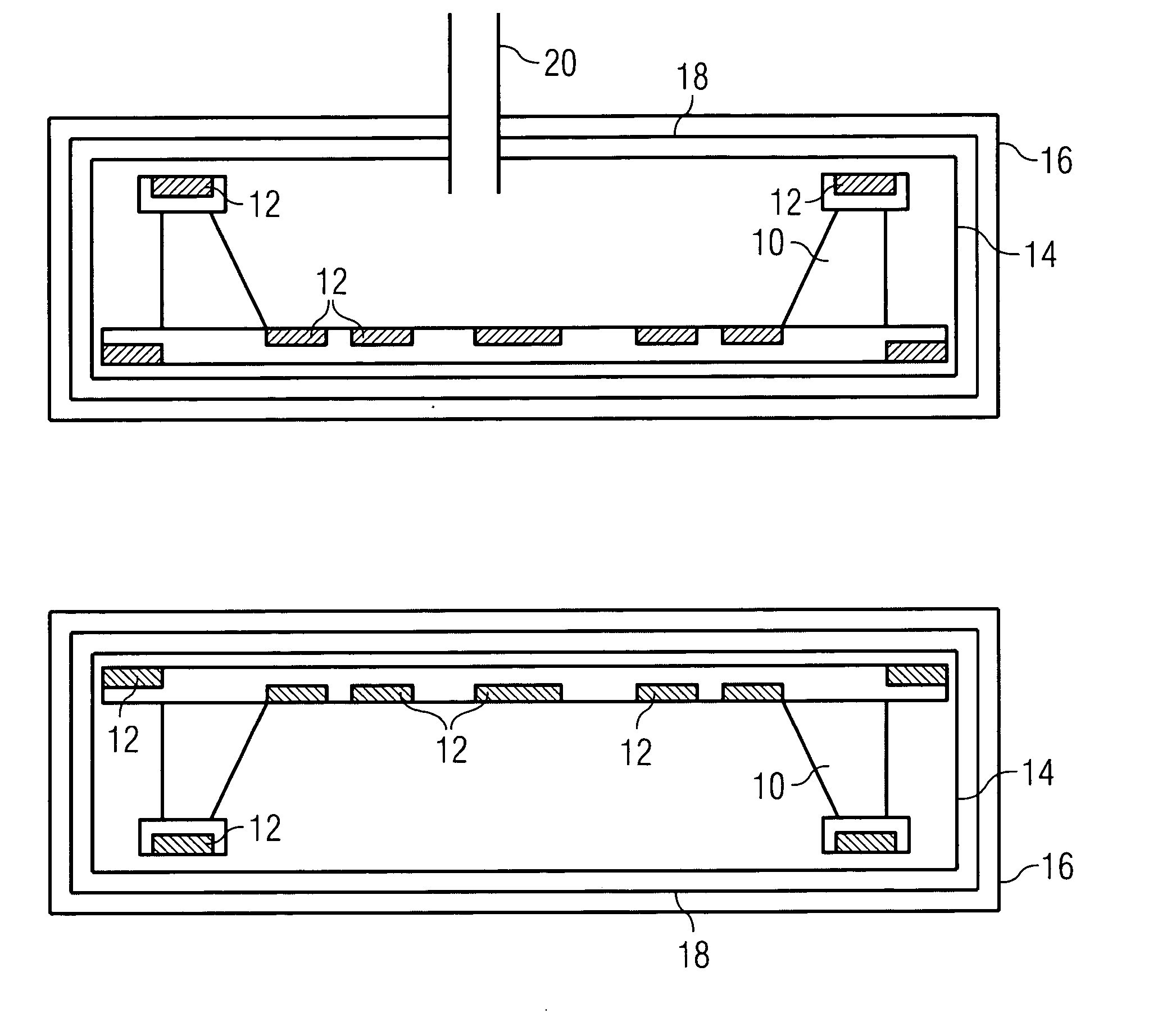
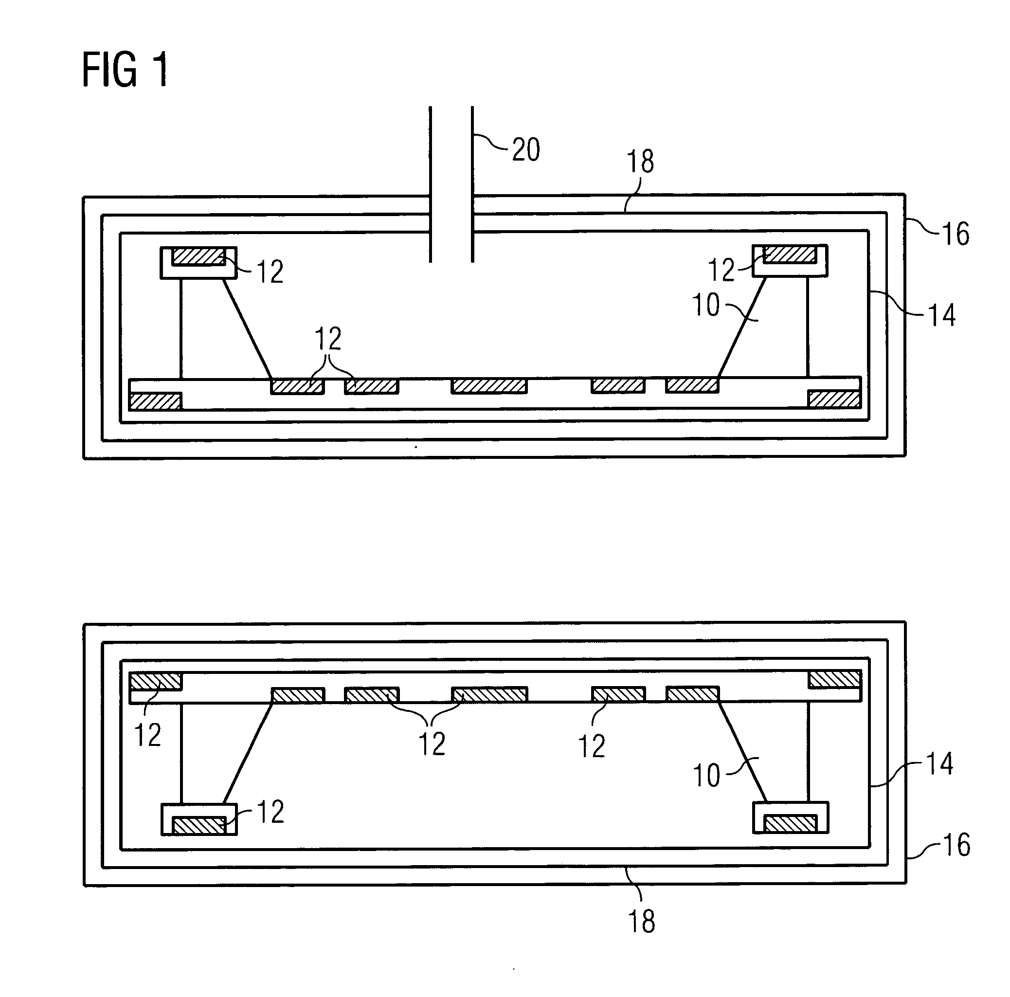
[0030] In the simplest embodiment of the present invention, the structure of FIG. 1 is unchanged. The cryogen vessel 14 is partially filled with a second cryogen, such as nitrogen. This may be achieved by filling with liquid nitrogen, or by operating an associated recondensing refrigerator to liquid nitrogen temperature and leaving the cryogen vessel open to an appropriate source of nitrogen. Once a required volume of second cryogen has been introduced, a required volume of working cryogen such as helium is introduced. The system may now be held at operating temperature by an associated recondensing refrigerator. The second cryogen will remain solid within the cryogen vessel, and will take no active part in maintaining the system at operating temperature.

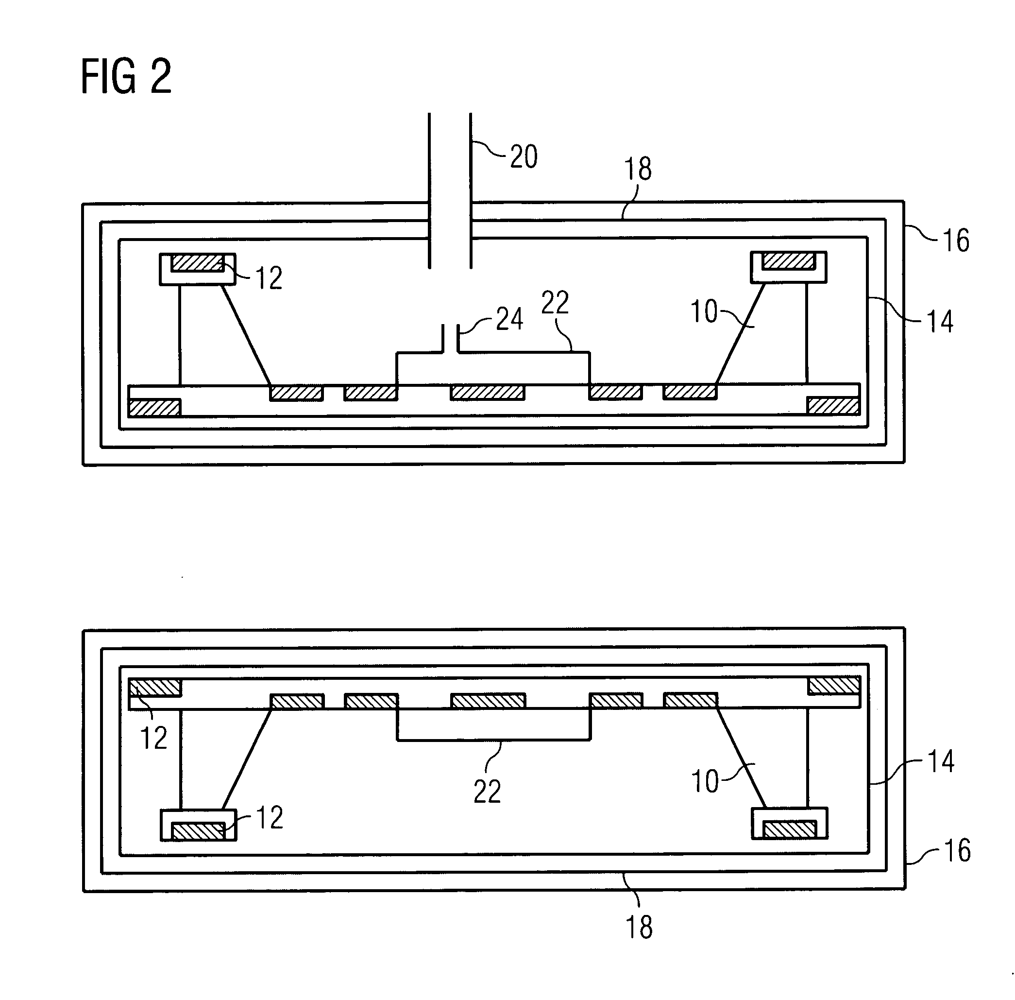
[0031] If the recondensing refrigerator stops for some reason, for example because the system is being transported, the working cryogen will boil off, cooling the system. If the working cryogen boils dry, the second cryogen will be...


PUM


Abstract

The present provides a cryogenic thermal battery arrangement for maintaining a superconducting magnet coil or similar apparatus at cryogenic temperature for a required shipping period, such as thirty days, without consuming a significant amount of costly cryogen. According to another aspect, the invention allows extended shipping periods without incurring excessive costs.

Description

[0001] The present invention relates to a thermal battery, that is, a device which serves to hold a piece of equipment at a certain temperature without external refrigeration and despite a relatively elevated ambient temperature. BACKGROUND OF THE INVENTION [0002] Superconducting magnets are well known and used for producing very high strength magnetic fields in applications such as magnetic resonance imaging. The superconducting magnet is typically made up of a number of coils of superconducting wire which, in use, must be held at cryogenic temperatures typically of the order of 4K, the boiling point of liquid helium. Alternatively, systems using so-called high temperature superconductors are known. These may operate at the temperature of boiling neon, hydrogen or nitrogen. Critical temperatures in the region of 18-80K are typical for such materials. While the present invention will be described with particular reference to systems operating at about 4K, which are cooled by boiling...

Claims


Application Information

Patent Timeline
Patent Type & Authority Applications(United States)
IPC IPC(8): F17C13/00F25D3/08
CPCF17C2203/0629G01R33/3815F17C2205/0157F17C2221/014F17C2221/017F17C2223/0161F17C2223/033F17C2270/0527F17C2270/0536F25D9/00F25D2303/082G01R33/3802G01R33/3804H01F6/04F17C2205/0149
Inventor ATKINS, ANDREW FARQUHARGILGRASS, GRAHAMSTAUTNER, WOLFGANG
Owner SIEMENS HEALTHCARE LTD
Why Eureka
Try Eureka