Marine bottomed tensioned riser and method

a technology of tensioning riser and bottom, which is applied in the direction of drilling pipes, well accessories, sealing/packing, etc., can solve the problems of tlp still moving laterally, saturating diving, and needing to be positioned properly using pile-driving technology, etc., to simplify the deepwater challenge, the effect of requiring space is readily available and the effect of significant technical benefits

Inactive Publication Date: 2006-09-12
BP CORP NORTH AMERICA INC
View PDF17 Cites 14 Cited by
  • Summary
  • Abstract
  • Description
  • Claims
  • Application Information

AI Technical Summary

Benefits of technology

[0017]The BTR can be designed to meet a wide range of Host Facility motions throughout the field development life, and it eliminates the need for disconnecting the vertical export / import riser. This is made possible by virtue of a coil section, which is located in the lower portion of the riser system. One unique aspect of the invention is that it solves a riser system application problem that has normally been approached from the surface / Host Facility (i.e., from the top down). The BTR concept, which approaches the top tension problem from the bottom up, provides a solution that has both technical and cost benefits.
[0018]The technical benefits include its use as a vertical riser system. The vertical riser system projection onto the seabed is low when compared to other methods. By virtue of this, it simplifies the seabed architecture. Simplicity in deepwater operations is directly related to the magnitude of risk of unplanned occurrences happening. The vertical riser design can be performed using analysis techniques and assumptions that are proven. The time required to do the analysis of a vertical riser is roughly one-half that of a SCR. The reason that the SCR requires so much more time is that it is a relatively new type of riser itself. Specialized and proprietary analysis methods are required for demonstrating riser fatigue life at the SCR touchdown point. The SCR touchdown point and lift-off modeling remains an area that is under research work to better resolve uncertainties about the models and their required assumptions. A SCR also requires proprietary modeling that is related to vortex-induced-vibrations (VIV). Since the riser shape is not vertical through the water column, VIV modeling cannot be performed in the traditional ways. Research work in this area of modeling is also continuing. The BTR concept can be designed to impose a relatively low top tensile load on the Host Facility. This tensile load change can be designed to be relatively small as the Host Facility goes through its full range of motions. This feature reduces the risks that are associated with predicting both the riser system maximum tensile stress and the fatigue design life that results from stress cycles. The BTR design can be configured to be forgiving without incurring excessive costs. If Host Facility motions are not identical to analytical predictions or model basin simulations, the BTR can be configured to provide a conservative design margin to allow for the differences from these predictions.
[0023]In the case of export and import risers, the BTR invention may provide cost benefit over alternative riser solutions. And when compared to present methods, the technical benefits may also be significant, especially for deepwater configurations that use seabed equipment that is located under the Host Facility.
[0024]The BTR system is one way to simplify the deepwater challenge. Riser top tensile stresses for this new system are shown in FIG. E-4B of the U.S. provisional patent application filed on Apr. 26, 2002 under Ser. No. 60 / 375,619). That figure shows that the new rigid riser system can provide a relatively low top tensile stress level across the range of possible Host Facility motions.

Problems solved by technology

However, saturation diving, which is necessary beyond 180 feet of water, is costly and there can be safety issues to consider as well.
Due to soft bottom conditions that prevail to several hundred feet below the seabed in many parts of the Gulf of Mexico, proper placement of these conductors using pile-driving technology can be a challenge.
However, even though the heave motions are small, the TLP will still move laterally due to its response to environmental loadings.
The riser tensioning systems add complexity and weight to the Host Facility, but allow retaining the “dry” features.

Method used


Image

  • Marine bottomed tensioned riser and method
  • Marine bottomed tensioned riser and method
  • Marine bottomed tensioned riser and method

Examples


Embodiment Construction

[0037]While this invention is susceptible of embodiment in many different forms, there is shown in the drawings, and will herein be described in detail, one specific embodiment of the invention. It should be understood, however, that the present disclosure is to be considered an exemplification of the principles of the invention and is not intended to limit the invention to any specific embodiment so described.

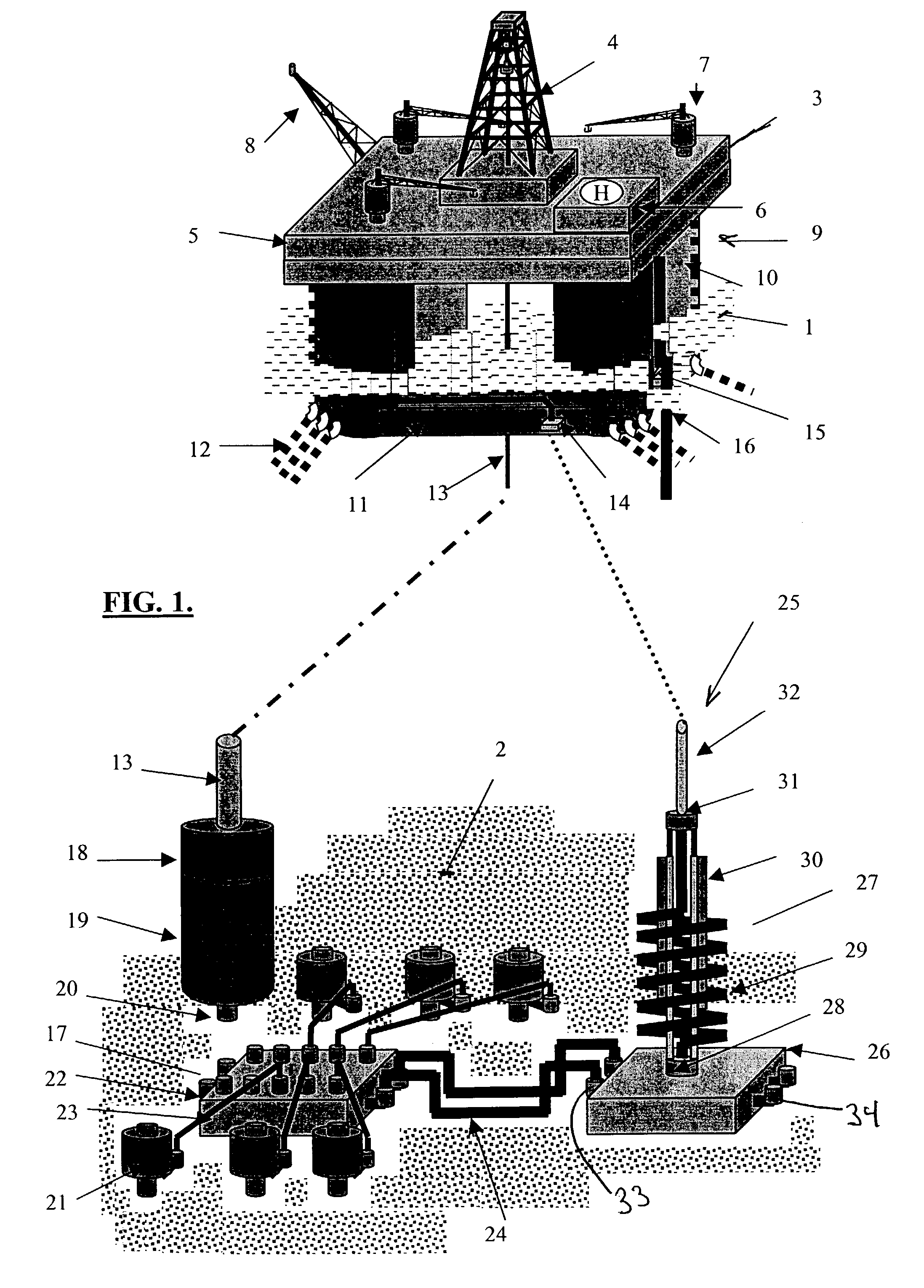
[0038]Turning to FIG. 1, the invention, and the overall environment of one embodiment of the invention is illustrated. At the upper half of the drawing is shown a Host Facility in the form of a semi-submersible platform and a floating production system 3 Production Drilling Quarters (PDQ). The PDQ comprises a drilling rig 4, topsides 5, crew quarters 6, cranes 7, and an emergency flare 8. The superstructure of the PDQ is supported by columns 10 which are connected to pontoons 11 which are submerged below the surface 1 of the water. The PDQ is positioned by mooring lines 12 whi...


PUM


Abstract

A new marine oil production riser system for use in deepwater applications is disclosed. An efficient means for accommodating movements of the host facility, while maintaining riser top tension within the limits for long-term riser performance. Long riser stroke lengths can be accommodated without requiring complex interfacing with the topsides. The riser assembly comprises: a generally extendable substantially non-vertical section having an upper end adapted to be in flow communication with a generally vertical marine riser carried by a facility floating on the surface of a body of water, and having a lower end adapted to be in flow communication with a fluid source on the seafloor; and tensioning means, mechanically connecting the upper end of the marine riser with the lower end of the marine riser, for biasing said ends towards each other. The tensioning means comprises: a cylinder having one end open to sea pressure, having an opposite end sealed from sea pressure, and connected to one end of the marine riser; a piston within the cylinder disposed for movement within the cylinder; and a piston rod passing through the opposite end of the cylinder and having one end connected to the other end of the marine riser.

Description

CROSS-REFERENCE TO RELATED APPLICATIONS[0001]This application claims the benefit under 35 USC §119(e) of a United States (US) provisional patent application filed on Apr. 26, 2002 under Ser. No. 60 / 375,619 whose contents are incorporated by reference.TECHNICAL FIELD[0002]This invention relates to the general subject of production of oil and gas and, in particular, to marine risers used in the production of oil and gas from the seabed.STATEMENT REGARDING FEDERALLY SPONSORED RESEARCH OR DEVELOPMENT[0003]Not applicable.REFERENCE TO A “MICROFICHE APPENDIX”[0004]Not applicable.BACKGROUND OF THE INVENTION[0005]Marine riser technology and its development have been driven by two basic needs in the oil industry.[0006]The first need has been to resolve the challenges that are related to using drilling risers during exploratory drilling. These risers bridge between the seabed and the surface when doing exploration drilling from a floating vessel, which is normally either a semi-submersible dri...

Claims


Application Information

Patent Timeline
Patent Type & Authority Patents(United States)
IPC IPC(8): E21B29/12E21B19/00
CPCE21B19/002
Inventor KLEINHANS, JOHN W.
Owner BP CORP NORTH AMERICA INC
Why Eureka
Try Eureka