
Method and apparatus for hole punching

Inactive Publication Date: 2006-12-28
SHOWA DENKO KK
View PDF10 Cites 9 Cited by
  • Summary
  • Abstract
  • Description
  • Claims
  • Application Information

AI Technical Summary

Benefits of technology

[0007] In the aforementioned conventional hole punching method, the remained material is required to be removed by punching after the full enclosed die forging, which requires a high forming load to prevent occurrence of underfill at the time of forging and results in low yield of materials.

Problems solved by technology

In the aforementioned conventional hole punching method, the remained material is required to be removed by punching after the full enclosed die forging, which requires a high forming load to prevent occurrence of underfill at the time of forging and results in low yield of materials.

Method used


Image

  • Method and apparatus for hole punching
  • Method and apparatus for hole punching
  • Method and apparatus for hole punching

Examples


Embodiment Construction

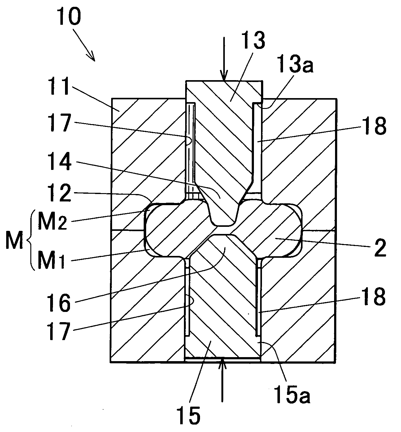
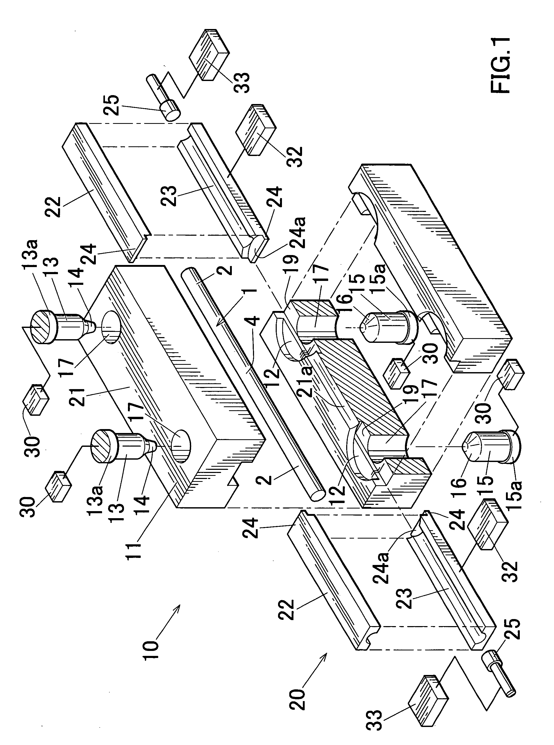
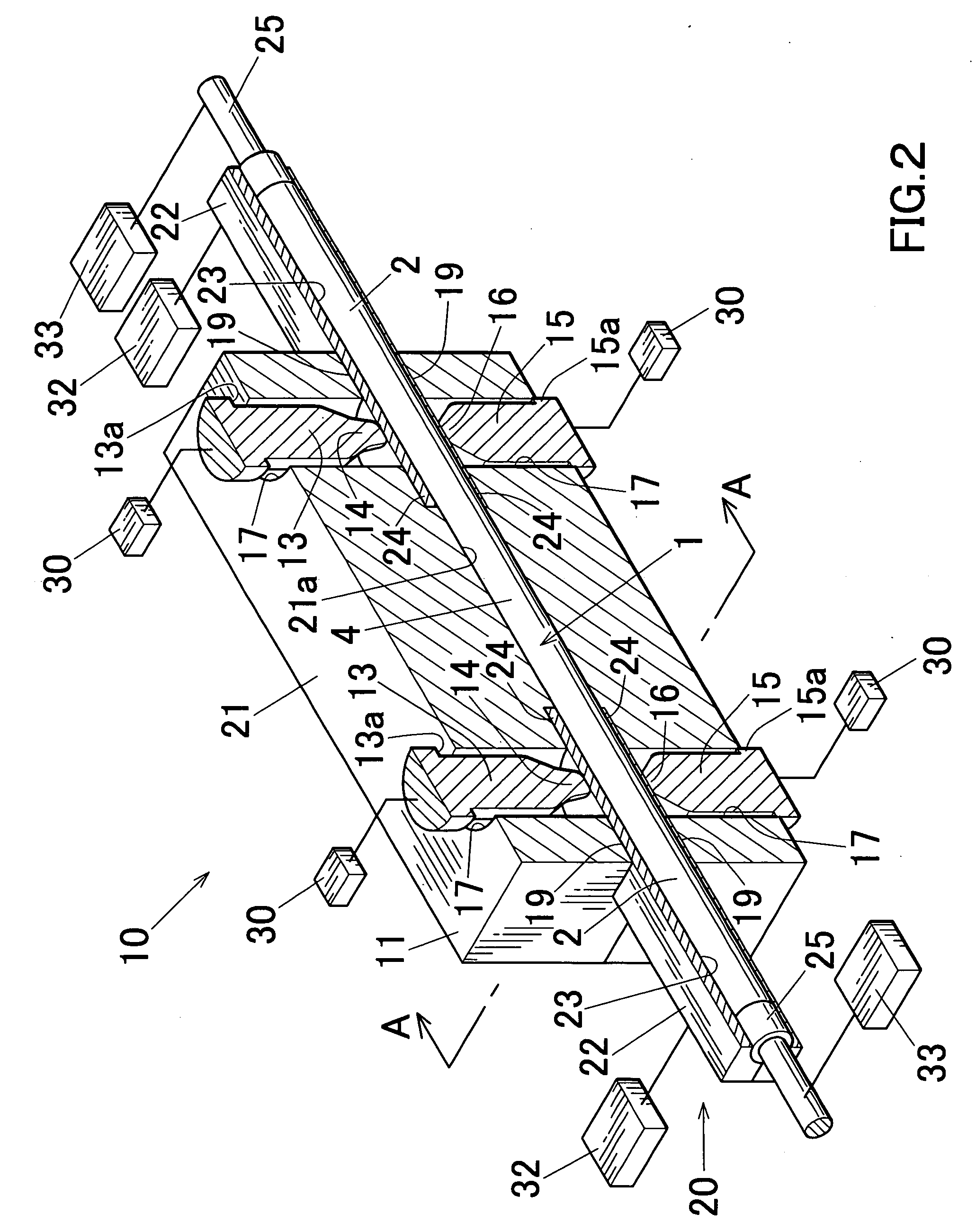
[0065] Next, an embodiment of the present invention will be explained below with reference to the attached drawings.

[0066] In FIG. 1, “10” denotes a hole punching apparatus according to this embodiment, and “1” denotes a raw material. Furthermore, in FIG. 13, “6” denotes a hole punched product (hole punched article) manufactured with the hole punching apparatus 1. This hole punched product 6 is used as a preform for manufacturing arms for vehicles, such as, e.g., automobiles or railroad vehicles.

[0067] As shown in FIG. 1, the raw material 1 is a straight bar-shaped member made of, e.g., aluminum (including its alloy). The raw material 1 is circular in cross-section and constant in cross-sectional area along the axial direction.

[0068] In the present invention, the quality of material of the raw material 1 is not limited to aluminum, and can be metal, such as, e.g., brass, copper, or stainless steel, or plastic. Moreover, the cross-sectional configuration of the raw material 1 is n...


PUM

PropertyMeasurementUnit
Angleaaaaaaaaaa
Diameteraaaaaaaaaa

Abstract

A hole punching method capable of executing hole punching with high material yield at a low load and preventing occurrence of underfill is provided. The hole punching method includes a step of expanding a hole punching scheduled portion 2 of a raw material 1 disposed in a cavity 12 of a closed die 11 by pressing the hole punching scheduled portion 2 from opposite sides thereof across the hole punching scheduled portion 2 with a pair of large diameter punch and small diameter punch 13 and 15 different in diameter and arranged to as to face each other so that unfilled portions remain in the cavity, a step of penetrating the small diameter punch 13 into the hole punching scheduled portion 2 of the raw material 1 while releasing or after releasing pressurization by the large diameter punch 15 to the hole opening scheduled portion 2, and a step of penetrating the large diameter punch15 into the hole punching scheduled portion 2 of the raw material 1 while pulling out or after pulling out the small diameter punch 13 penetrated in the hole punching scheduled portion 2 of the raw material 1 from the hole punching scheduled portion 2 of the raw material 1.

Description

[0001] This application claims priority to Japanese Patent Application No. 2005-153770 filed on May 26, 2005, and U.S. Provisional Application No. 60 / 685,870 filed on Jun. 1, 2005, the entire disclosures of which are incorporated herein by reference in their entireties. CROSS REFERENCE TO RELATED APPLICATIONS [0002] This application is an application filed under 35 U.S.C. §111(a) claiming the benefit pursuant to 35 U.S.C. §119(e)(1) of the filing date of U.S. Provisional Application No. 60 / 685,870 filed on Jun. 1, 2005, pursuant to 35 U.S.C. §111(b).FIELD OF THE INVENTION [0003] The present invention relates to a method and an apparatus for hole punching for use in manufacturing hole punched products, such as, e.g., arms or connecting rods for vehicles (e.g., automobiles, or railroad vehicles). DESCRIPTION OF THE RELATED ART [0004] Conventionally, in manufacturing hole punched products by forging, from the viewpoint of die life and safety, in place of directly executing hole punchin...

Claims


Application Information

Patent Timeline
IPC IPC(8): B21D31/02
CPCB21J5/02B21J5/10B21J5/08
Inventor OTAKI, ATSUSHI
Owner SHOWA DENKO KK
Learn More