Substrate heat treatment apparatus

a heat treatment apparatus and substrate technology, applied in the direction of charge manipulation, furnaces, muffle furnaces, etc., can solve the problems of unevenness, inability to make full use of the highly precise temperature uniformity, and the minute space between the bake plate and the substrate cannot be uniform over the entire surface of the substrate, so as to achieve the effect of increasing the uniformity

Active Publication Date: 2006-12-28
DAINIPPON SCREEN MTG CO LTD
View PDF6 Cites 22 Cited by
  • Summary
  • Abstract
  • Description
  • Claims
  • Application Information

AI Technical Summary

Benefits of technology

[0024] With this construction, the seal unit closes the side of minute space between the lower surface of the substrate and the upper surface of the bake plate. When gas is exhausted from the minute space through the exhaust bores, a negative pressure is produced by the gas leaving an entire expanse under the minute space through the porous member. The negative pressure draws the substrate toward the bake plate. Thus, any curvature of the substrate is leveled, so that the lower surface of the

Problems solved by technology

Thus, however accurately uniform a temperature distribution may be made over the surface of the bake plate, when a substrate is actually heated in the semiconductor manufacturing process, the minute space between the bake plate and substrate cannot be uniform over the entire surface of the substrate, but becomes uneven.
This results in a problem that the heat treatment of the substrate is conducted without making full u

Method used


Image

  • Substrate heat treatment apparatus
  • Substrate heat treatment apparatus
  • Substrate heat treatment apparatus

Examples


embodiment 1

[0042] Embodiment 1 of this invention will be described hereinafter with reference to the drawings.

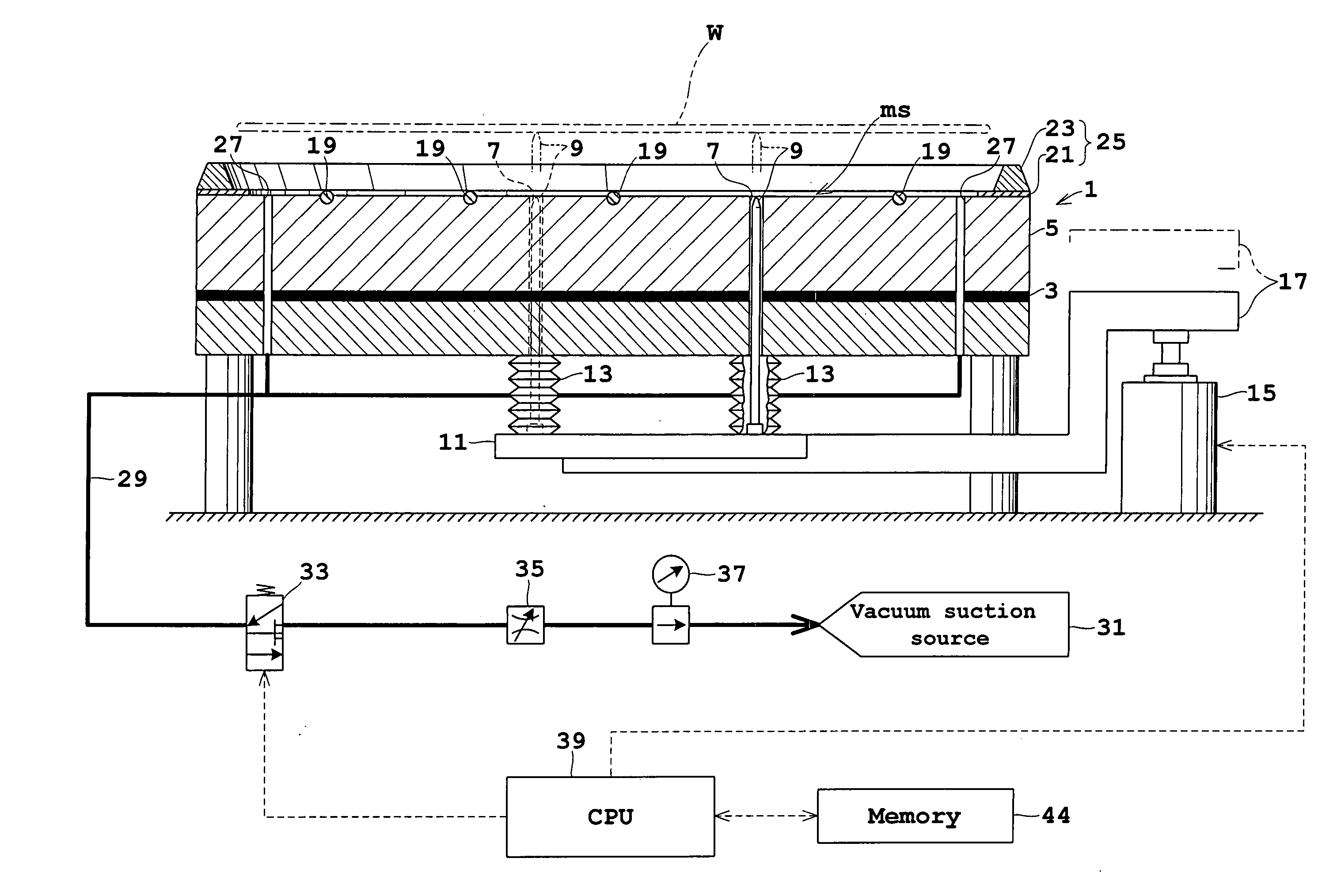
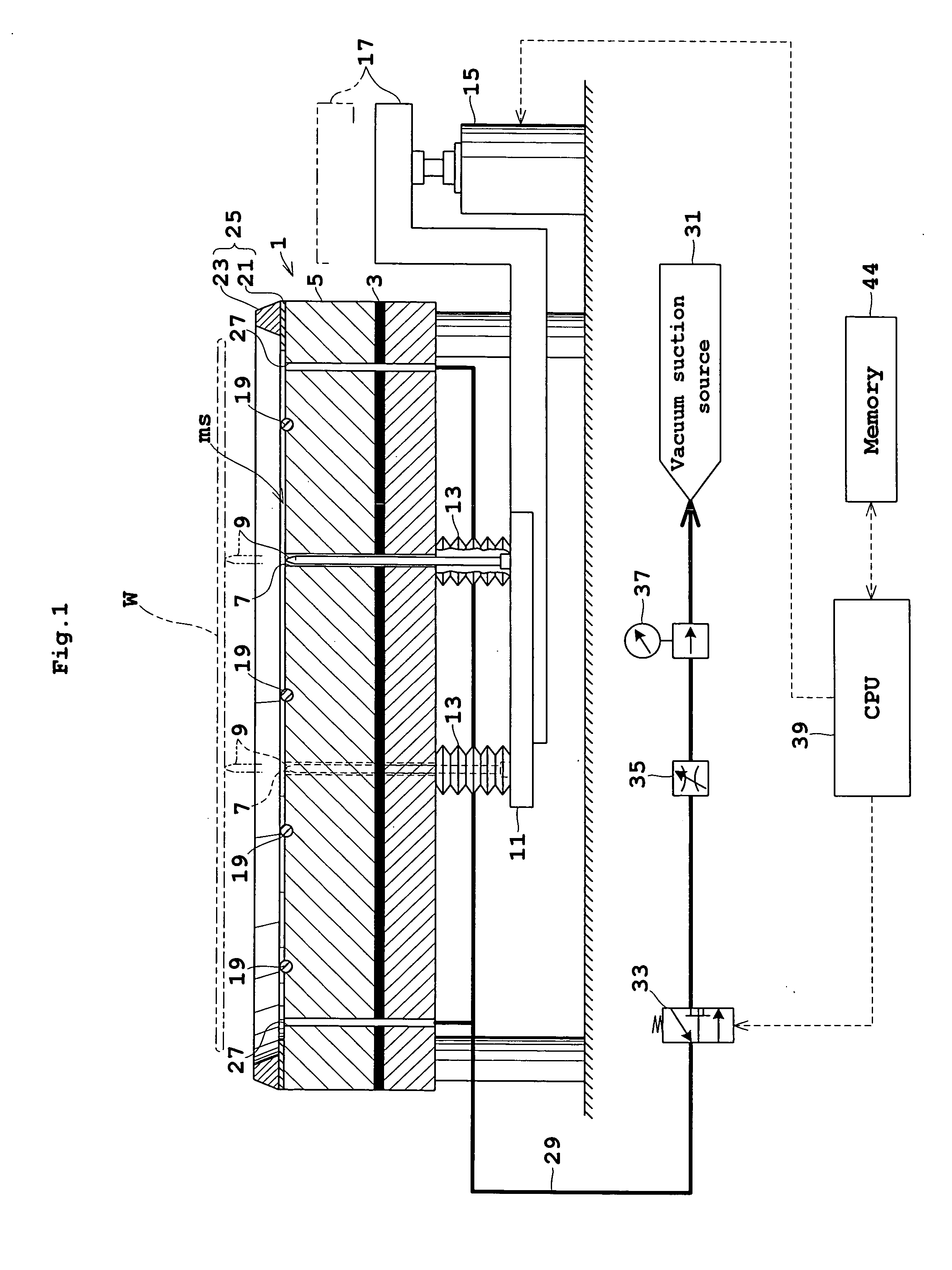
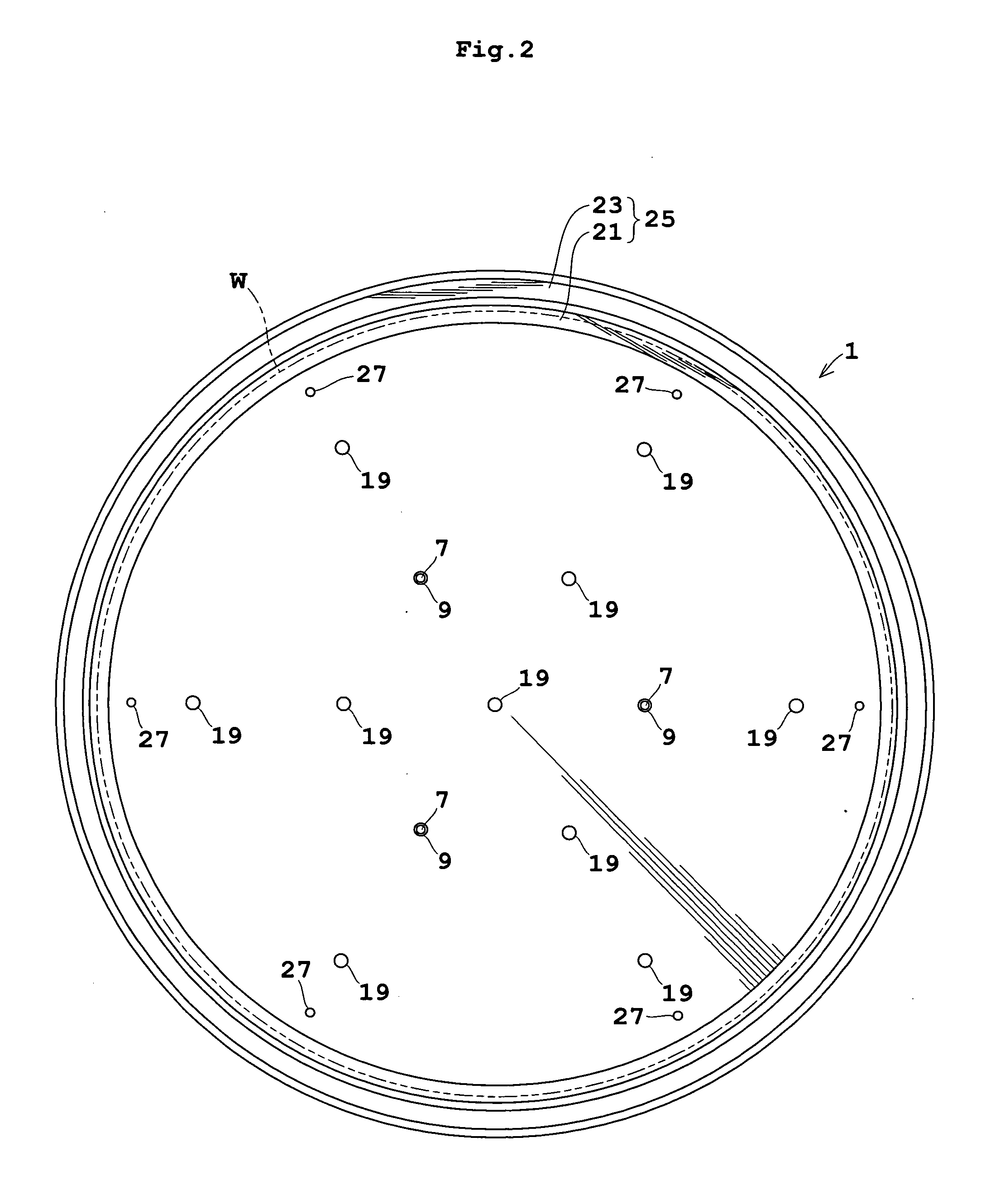
[0043]FIG. 1 is a view in vertical section showing an outline of a substrate heat treatment apparatus in Embodiment 1. FIG. 2 is a plan view of the apparatus shown in FIG. 1. FIG. 3 is an enlarged view in vertical section of a bake plate.

[0044] A bake plate 1 for supporting a substrate or wafer W on an upper surface thereof has a heating element 3 such as a mica heater mounted in a lower portion thereof. A heat transfer portion 5 between the heating element 3 and the upper surface of bake plate 1 has a plurality of heat pipes, not shown, embedded therein. Cooling grooves, not shown, are formed between the heat pipes for circulating a cooling fluid.

[0045] The bake plate 1 has three perforations 7 extending from the upper surface to the lower surface. These perforations 7 are formed in positions corresponding to the apexes of an equilateral triangle in plan view, each having a support...

embodiment 2

[0059] Next, Embodiment 2 of this invention will be described with reference FIG. 8. FIG. 8 is a view in vertical section showing an outline of a substrate heat treatment apparatus in Embodiment 2. In the following description, like reference numerals are used to identify like parts which are the same as in Embodiment 1 and will not particularly be described.

[0060] Embodiment 2 relates to an improvement made in the upper surface of bake plate 1A.

[0061] Specifically, the upper surface of bake plate 1A, and more particularly the upper surface of heat transfer portion 5A inwardly of the seal assembly 25, is recessed in a shape of shallow concave around the center. When the wafer W is curved to have the central part bulging downward from the periphery (bowl-like curvature), the central part may be drawn first, with only insufficient suction acting on the periphery. The recessed shape of the upper surface of bake plate 1A allows the periphery of wafer W to be fully drawn. Thus, regardl...

embodiment 3

[0062] Next, Embodiment 3 of this invention will be described with reference FIG. 9. FIG. 9 is an enlarged view in vertical section of a portion of a substrate heat treatment apparatus in Embodiment 3. Tike reference numerals are used to identify like parts which are the same as in Embodiment 1 described hereinbefore, and will not particularly be described.

[0063] Embodiment 3 is different from Embodiments 1 and 2 in the construction of a seal assembly 25A.

[0064] Specifically, the seal assembly 25A includes a support portion 21A and a regulator 23. The support portion 21A has a contact portion 43 and a groove 45. The contact portion 43 has an inside diameter slightly smaller than the outside diameter of wafer W, and an upper surface thereof contactable with a portion of the lower surface of wafer W slightly inward from the edge. The groove 45 is located outwardly of the contact portion 43 and does not contact the lower surface of wafer W.

[0065] When the wafer W is placed in the su...


PUM

PropertyMeasurementUnit
Pressureaaaaaaaaaa
Diameteraaaaaaaaaa
Shapeaaaaaaaaaa

Abstract

A substrate heat treatment apparatus for heat-treating a substrate includes a bake plate having projections on an upper surface thereof, a seal unit disposed peripherally of the upper surface of the bake plate for closing a lateral area of a minute space formed between a lower surface of the substrate and the upper surface of the bake plate when the substrate is placed on the bake plate, and exhaust bores for exhausting gas from the minute space. The substrate placed on the bake plate is heat-treated in a state of the gas exhausted from the minute space through the exhaust bores.

Description

BACKGROUND OF THE INVENTION [0001] (1) Field of the Invention [0002] This invention relates to a substrate heat treatment apparatus for heat-treating substrates such as semiconductor wafers and glass substrates for liquid crystal displays (hereinafter simply called substrates). More particularly, the invention relates to a technique for heat-treating a substrate slightly spaced from a bake plate instead of being in contact with the plate. [0003] (2) Description of the Related Art [0004] A conventional apparatus of the type noted above has a bake plate variable in temperature, and three balls arranged on an upper surface of the bake plate to be located at apexes of an equilateral triangle in plan view (as disclosed in Japanese Unexamined Patent Publication No. 2000-193376, for example). With this apparatus, a substrate placed on the bake plate is supported at a lower surface thereof by the three balls, so that the entire lower surface is separated by a minute space from the bake plat...

Claims


Application Information

Patent Timeline
IPC IPC(8): F27B5/14F27D11/00
CPCF27B5/04F27B17/0025F27D3/0084H01L21/6875H01L21/67126H01L21/68735H01L21/68742H01L21/67109H01L21/324
Inventor MORITA, AKIHIKOGOTO, SHIGEHIROMATSUCHIKA, KEIJI
Owner DAINIPPON SCREEN MTG CO LTD
Why Eureka
Try Eureka