
Computer-implemented methods for detecting and/or sorting defects in a design pattern of a reticle

a technology of computer implementation and design pattern, which is applied in the direction of semiconductor/solid-state device testing/measurement, instruments, photomechanical equipment, etc., can solve the problems of high inefficiency, difficult and consequently more expensive manufacturing of reticles, and electrical failures in wafer fabrication

Active Publication Date: 2006-12-28
KLA TENCOR TECH CORP
View PDF44 Cites 118 Cited by
  • Summary
  • Abstract
  • Description
  • Claims
  • Application Information

AI Technical Summary

Benefits of technology

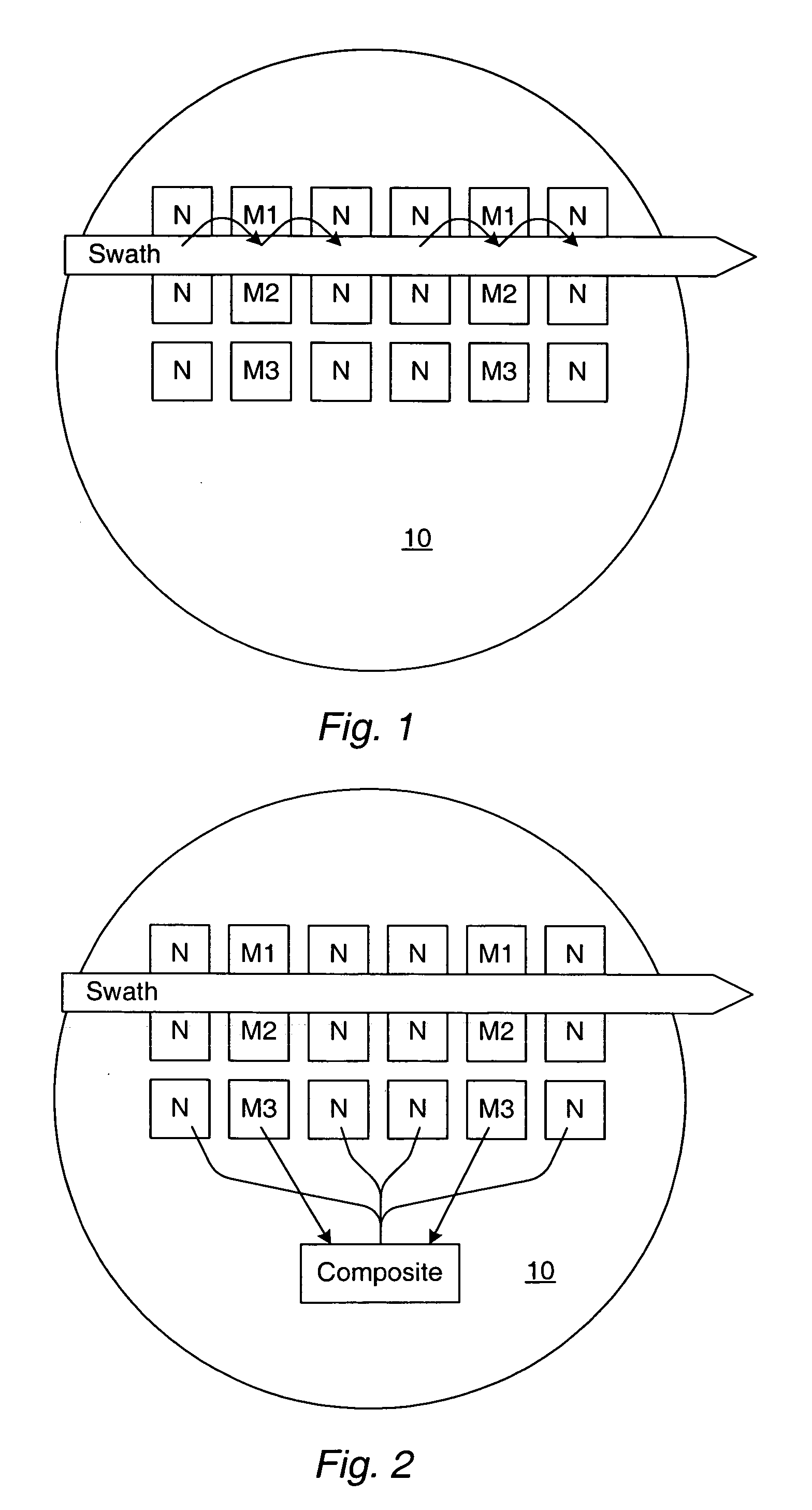
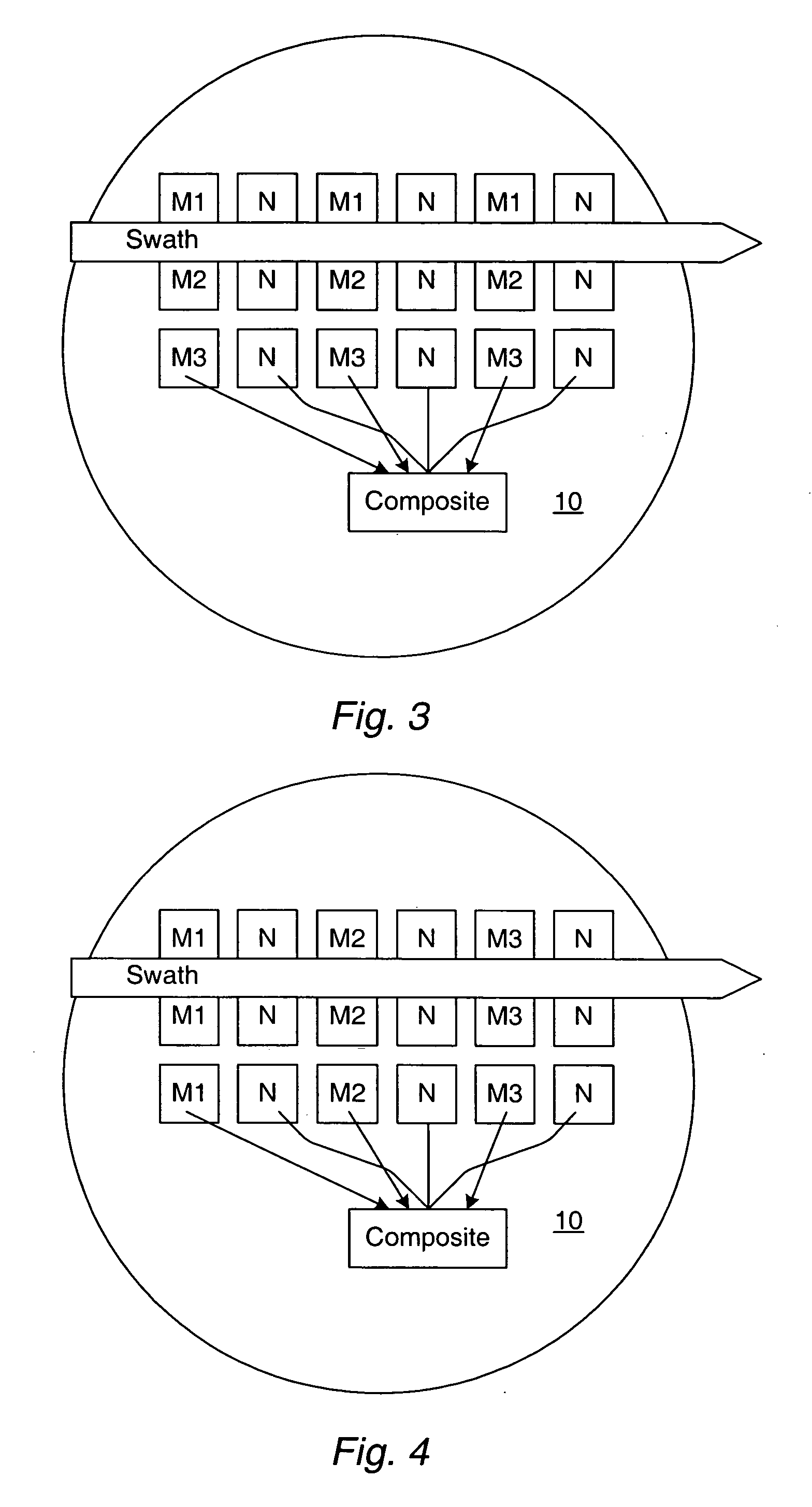
[0031] In one embodiment, the dies include modulated dies and at least one reference die. In another embodiment, the dies may include two or more reference dies as defined in the inspection recipe. In this embodiment, the method may also include generating a composite reference image from the images of the two or more reference dies. In such an embodiment, one of the at least two of the images used for the comparison includes the composite reference image. In an additional embodiment, the dies may include modulated dies and at least one reference die. Each of the embodiments of the method described above may include any other step(s) described herein.
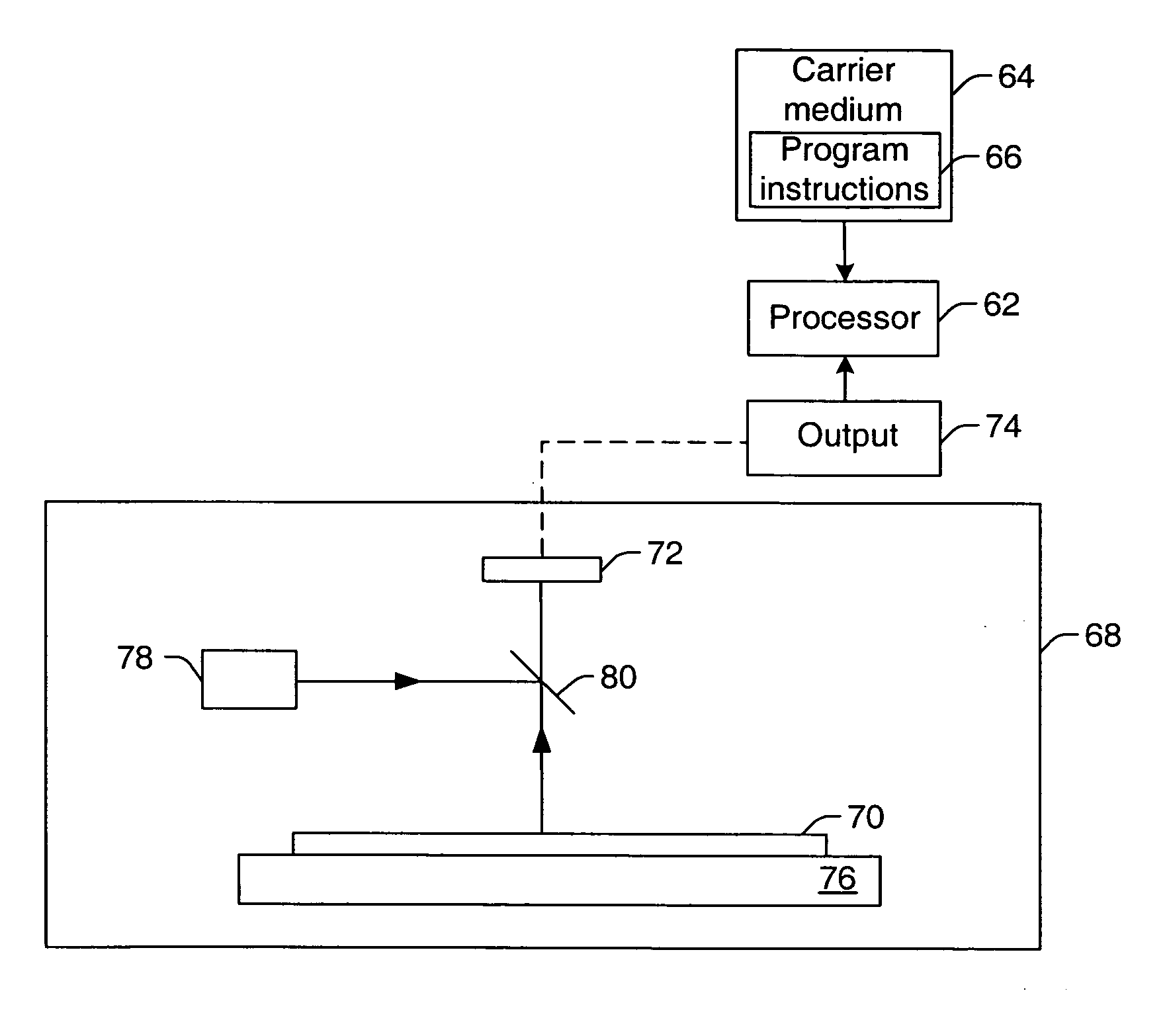
[0032] Further embodiments relate to a carrier medium that includes program instructions executable on a computer system to perform any of the computer-implemented methods described herein. Additional embodiments relate to a system configured to perform any of the computer-implemented methods described herein. The system may include a processor configured to execute program instructions for performing one or more of the computer-implemented methods described herein. In one embodiment, the system may be a stand-alone system. In another embodiment, the system may be a part of or coupled to an inspection system such as a wafer imaging system or an aerial imaging measurement system. In a different embodiment, the system may be a part of or coupled to a defect review system. In yet another embodiment, the system may be coupled to a fab database. The system may be coupled to an inspection system, a review system, and / or a fab database by a transmission medium such as a wire, a cable, a wireless transmission path, and / or a network. The transmission medium may include “wired” and “wireless” portions.

Problems solved by technology

Although they are implemented in semiconductor device designs to facilitate low k1 lithography, these RET make reticles more difficult and consequently more expensive to manufacture.
This set can be used to direct a point-to-point inspector, such as at a Review SEM, but this can be highly inefficient due to the number of critical points.
Marginal RET designs not noted by simulation checks translate into electrical failures in wafer fabrication, affect yield, and possibly remain unnoticed until wafer fabrication is complete.
Traditional methods employed in the inspection of complex mask patterns place tremendous demand on reticle inspection tools.
Performing an inspection of a conventional focus exposure matrix introduces a complication in that every exposure field is different.
Moreover, current reticle inspection techniques cannot detect the presence of an error in the design database.
Randomly occurring defects in either or both of the reference dies may adversely affect the results if they result in reducing the priority of defects in the modulated dies.
Unfortunately, by its very nature, the experiment can produce an overwhelming number of unimportant repeating defects, particularly in the dies that are highly modulated.
However, the inline ADC (iADC) method that is available for PWQ uses additional information about the defect itself, and much of this information is irrelevant to finding the most likely failure points.
However, in these methods, a user selects background features from the complete set of available features that are used to classify defects thereby creating an extra step in the setup of the inspection.
Additionally, in current methods for reviewing defects, it is difficult to obtain multiple examples of potentially interesting defects.
However, there are disadvantages to using such a golden die image.
On the other hand, the detail of the golden die image may be reduced, but compromising on the detail of the golden die image compromises the effectiveness of the inspection method.
The differences in formation of the golden die and the modulated dies may result in false defect detection during inspection of the modulated dies.
Moreover, reading the golden image from storage media can be slower that reacquiring the golden image from an image computer or another computer system.

Method used


Image

  • Computer-implemented methods for detecting and/or sorting defects in a design pattern of a reticle
  • Computer-implemented methods for detecting and/or sorting defects in a design pattern of a reticle
  • Computer-implemented methods for detecting and/or sorting defects in a design pattern of a reticle

Examples


Embodiment Construction

[0040] As used herein, the term “defect” refers to a defect in a design pattern of a reticle that may cause a defect in a design pattern printed on a wafer using the reticle such as excessive corner rounding, unsatisfactory dimensions, missing features, bridging between features, etc. In particular, the methods described herein are particularly suitable for detecting defects in resolution enhancing technology (RET) features of the design pattern.

[0041] The terms “reticle” and “mask” are used interchangeably herein. A reticle generally includes a transparent substrate such as glass, borosilicate glass, and fused silica having a layer of opaque material formed thereon. The opaque regions may be replaced by regions etched into the transparent substrate.

[0042] Many different types of reticles are known in the art, and the term reticle as used herein is intended to encompass all types of reticles. For example, the term reticle refers to different types of reticles including, but not li...


PUM


Abstract

Various computer-implemented methods are provided. One method for sorting defects in a design pattern of a reticle includes searching for defects of interest in inspection data using priority information associated with individual defects in combination with one or more characteristics of a region proximate the individual defects. The priority information corresponds to modulation levels associated with the individual defects. The inspection data is generated by comparing images of the reticle generated for different values of a lithographic variable. The images include at least one reference image and at least one modulated image. A composite reference image can be generated from two or more reference images. The method also includes assigning one or more identifiers to the defects of interest. The identifier(s) may include, for example, a defect classification and / or an indicator identifying if the defects of interest are to be used for further processing.

Description

BACKGROUND OF THE INVENTION [0001] 1. Field of the Invention [0002] The present invention generally relates to computer-implemented methods for detecting and / or sorting defects in a design pattern of a reticle. Certain embodiments relate to a computer-implemented method that includes generating a composite reference image from two or more reference images and using the composite reference image for comparison with other sample images for defect detection. Other embodiments include sorting defects using priorities, defect attributes, defect appearance and background information. Additional embodiments relate to assisting the user in locating the relevant and unique defects based on background appearance and other characteristics combined with wafer design data and knowledge of process modulation. [0003] 2. Description of the Related Art [0004] The following description and examples are not admitted to be prior art by virtue of their inclusion in this section. [0005] The rapid decreas...

Claims


Application Information

Patent Timeline
Patent Type & Authority Applications(United States)
IPC IPC(8): G06K9/00
CPCG01N21/95607G01N2021/95676G03F7/70666G03F7/7065G03F1/84H01L21/0273
Inventor WU, KENONGRANDALL, DAVIDNAFISI, KOUROSHYNZUNZA, RAMONPETERSON, INGRID B.TRIBBLE, ARIELKOWALSKI, MICHALGAO, LISHENGKULKARNI, ASHOK
Owner KLA TENCOR TECH CORP
Learn More