Thermal imaging and laser scanning systems and methods for determining the location and angular orientation of a hole with an obstructed opening residing on a surface of an article

Inactive Publication Date: 2006-12-28
UNITED TECH CORP
View PDF7 Cites 32 Cited by
  • Summary
  • Abstract
  • Description
  • Claims
  • Application Information

AI Technical Summary

Benefits of technology

[0015] In a method of the present invention, a radiant heater and a thermal imaging system including an infrared camera and a scanning system including a laser spot projector, a laser spot sensor, a memory device and a processor are provided. An article containing obstructed holes is uniformly heated with a radiant heater until a nearly steady temperature is maintained. The infrared camera captures both a two-dimensional, black and white digital image and a one-dimensional, infrared digital image of the article for storage in the memory device. Since the holes are cooler than the surrounding article surface, a large temperature gr

Problems solved by technology

The identification of these candidate holes for use in th

Method used


Image

  • Thermal imaging and laser scanning systems and methods for determining the location and angular orientation of a hole with an obstructed opening residing on a surface of an article
  • Thermal imaging and laser scanning systems and methods for determining the location and angular orientation of a hole with an obstructed opening residing on a surface of an article
  • Thermal imaging and laser scanning systems and methods for determining the location and angular orientation of a hole with an obstructed opening residing on a surface of an article

Examples


Embodiment Construction

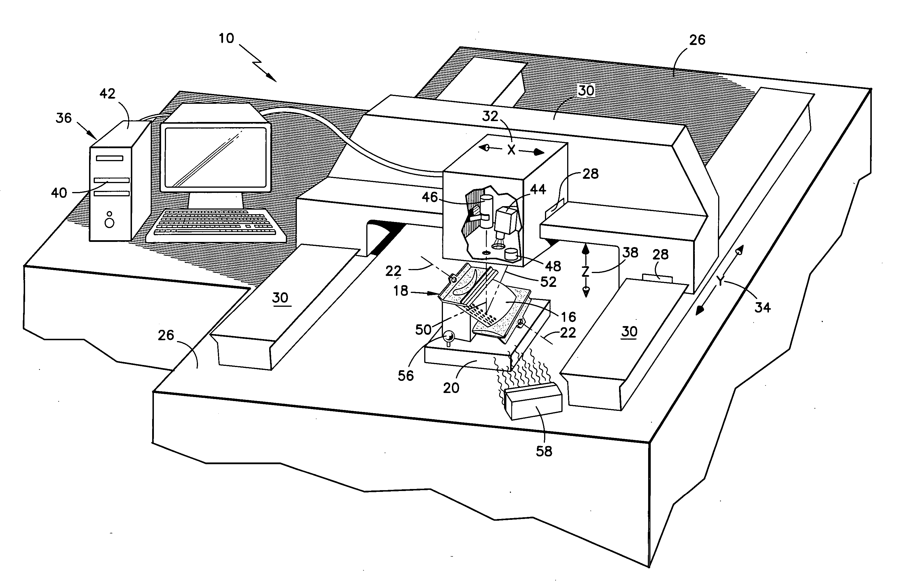
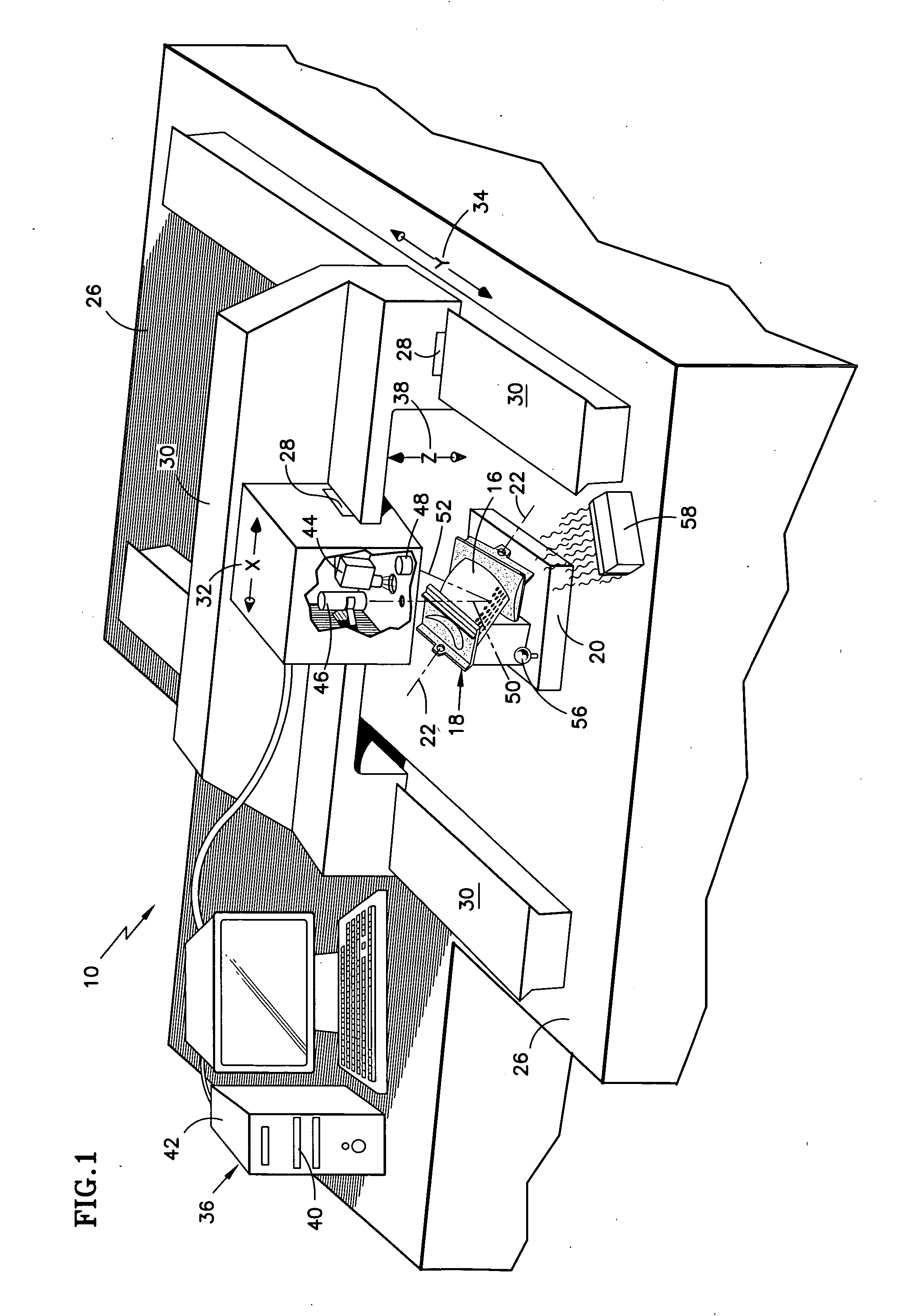
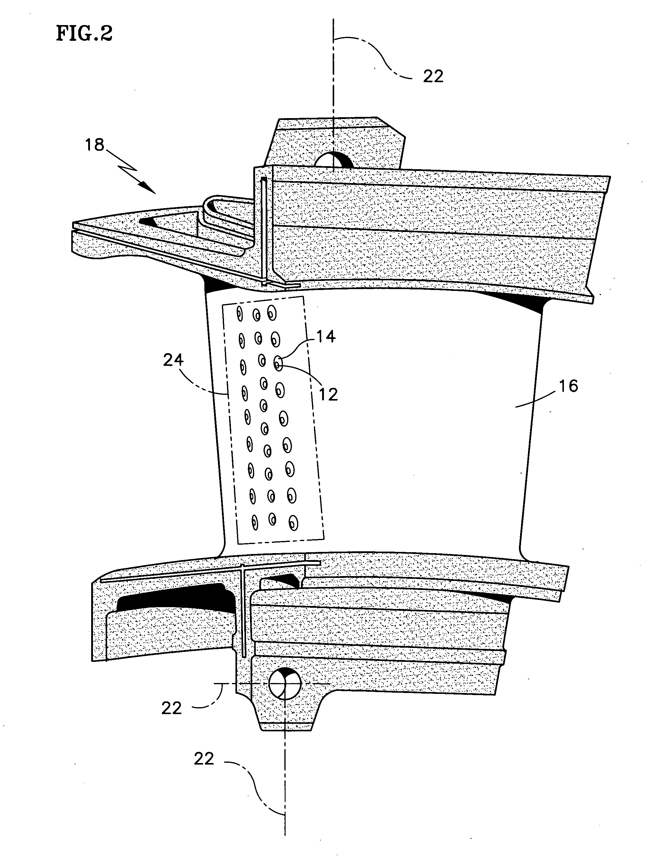
[0026] As illustrated in FIG. 1, a thermal imaging and laser scanning system 10 of the present invention is used to determine the location and angular orientation of one or more holes 12 with obstructed openings 14 on a surface 16 of a typical article 18 as illustrated in FIG. 2. In the example shown, the article 18 is a vane for use inside a gas turbine engine. The thermal imaging portion of system 10 is initially used to identify one or more candidate holes 12 for further processing by the laser-scanning portion of system 10. The candidate holes 12 have the least amount of obstruction and therefore contain more useable information about the hole location and angular orientation. By identifying candidate holes 12 in a given hole pattern using the thermal imaging portion of system 10, the processing time required by the laser-scanning portion of system 10 is substantially reduced.

[0027] In system 10, a stationary fixture 20 accurately establishes the location of the article 18 acco...


PUM

PropertyMeasurementUnit
Temperatureaaaaaaaaaa
Sizeaaaaaaaaaa
Gravityaaaaaaaaaa

Abstract

Provided are methods 100 and systems 10 for determining both the location and angular orientation of holes 12 with openings 14 on a surface 16 of an article 18 that are at least partially obstructed. In a method of the present invention, a thermal imaging and scanning system 10 that includes an infrared camera 44, a heater 58, a laser spot projector 46, a laser spot sensor 48, a memory device 40 and a processor 42 is provided. A digital, infrared pixel image of an article is acquired with the camera 44 while the article 18 is heated. Holes 12 with the least amount of obstruction are identified as candidate holes 12 for scanning. A laser beam 44 is projected onto the surface 16 of the article 18 in a region 24 containing at least one candidate hole 12 and the spot sensor 48 receives light reflections 52. A series of points 54 representing the scanned region 24 is stored as a point cloud 70 in the memory device 40. The point cloud 70 is then manipulated to calculate the location and angular orientation of each hole 12 in the region 24 in relation to one or more pre-existing, article datum 22.

Description

CROSS-REFERENCE TO RELATED APPLICATIONS [0001] This application discloses subject matter related to copending U.S. patent application “SYSTEMS AND METHODS FOR DETERMINING THE LOCATION AND ANGULAR ORIENTATION OF A HOLE WITH AN OBSTRUCTED OPENING RESIDING ON A SURFACE OF AN ARTICLE.” (APPLICANT REFERENCE NUMBER EH-11494), filed concurrently herewith.BACKGROUND OF THE INVENTION [0002] (1) Field of the Invention [0003] The invention relates to gas turbine engine components, and more particularly to systems and methods for determining the location and angular orientation of a hole containing an obstructed opening on a surface of such components. [0004] (2) Description of the Related Art [0005] Many internal components of gas turbine engines are exposed to gas temperatures that exceed their base material's melting temperature. For that reason, internal components such as turbine rotor blades, turbine vanes, combustor liners, shroud segments and the like must be thermally protected for imp...

Claims


Application Information

Patent Timeline
IPC IPC(8): G06K9/00G01M99/00
CPCB23P2700/06F01D5/005G01N21/9515G01N21/956G01N2021/8472G01N2021/8861F05D2260/202G06K9/28G06K2209/19G06T7/0004G06T7/004F05D2230/90G01N2021/8887G06T7/70G06V30/144G06V2201/06
Inventor VAIDYANATHAN, JANAKIRAMAN
Owner UNITED TECH CORP
Why Eureka
Try Eureka