Method for dispensing reagent onto a substrate

a technology of reagent and substrate, which is applied in the direction of liquid/solution decomposition chemical coating, laboratory glassware, instruments, etc., can solve the problems of affecting the performance of the test strip, the dispensing method is limited in the flexibility of independent adjustment and regulation of the output of the dispenser, and the application of one or more reagents to the test strip substrate is a highly difficult task. , to achieve the effect of improving performance and dynamic range of operation

Inactive Publication Date: 2006-12-28
BIODOT
View PDF60 Cites 36 Cited by
  • Summary
  • Abstract
  • Description
  • Claims
  • Application Information

AI Technical Summary

Benefits of technology

[0016] The reagent dispensing method and apparatus in accordance with the present invention can dispense desired quantities of chemical reagents or other liquids onto a substrate, such as a receptive membrane, while advantageously providing the ability to independently and precisely adjus

Problems solved by technology

Application of one or more reagents to a test strip substrate is a highly difficult task.
It is often difficult, however, to form sharp lines or other geometric shapes having uniform concentrations of reagent.
Currently available dispensing methods, however, are limited in the flexibility they have to independently adjust and regulate the output of the dispenser in terms of droplet size or mist quality, droplet velocity and flow rates of dispensed reagent.
This can cause undesirable lot to lot variances of reagent coating concentrations or coating patterns.
Often, however, a desired droplet size or mist quality is simply not attainable for a desired production flow rate.
This can increases the cost of production signific

Method used


Image

  • Method for dispensing reagent onto a substrate
  • Method for dispensing reagent onto a substrate
  • Method for dispensing reagent onto a substrate

Examples


Embodiment Construction

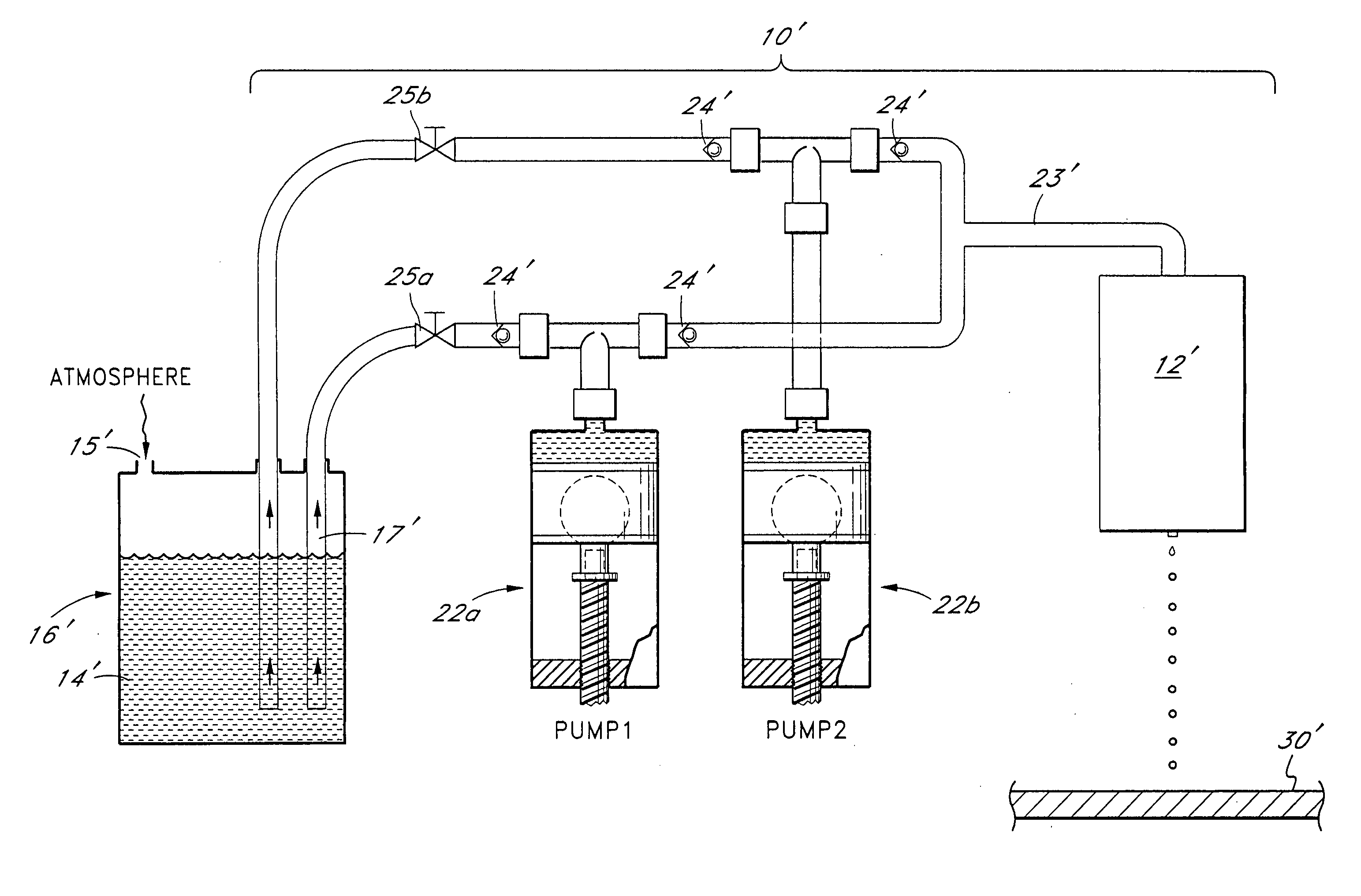
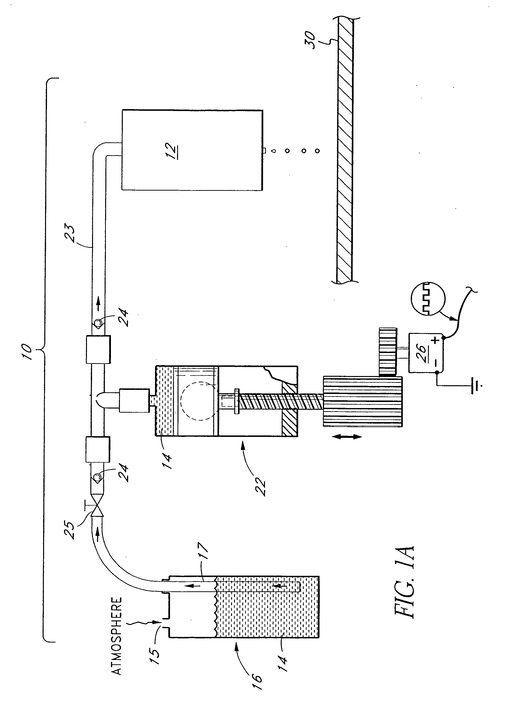
[0033]FIG. 1A is a schematic drawing of a precision metered dispensing apparatus 10 having features in accordance with the present invention. The dispensing apparatus 10 generally comprises a dispenser 12 for dispensing reagent 14 from a reservoir 16 and a positive displacement syringe pump 22 intermediate the reservoir 16 and the dispenser 12 for precisely metering the volume and / or flow rate of reagent dispensed. The dispenser 12 is operated to provide individual droplets or a spray of reagent, as desired, at the predetermined incremental quantity or flow rate.

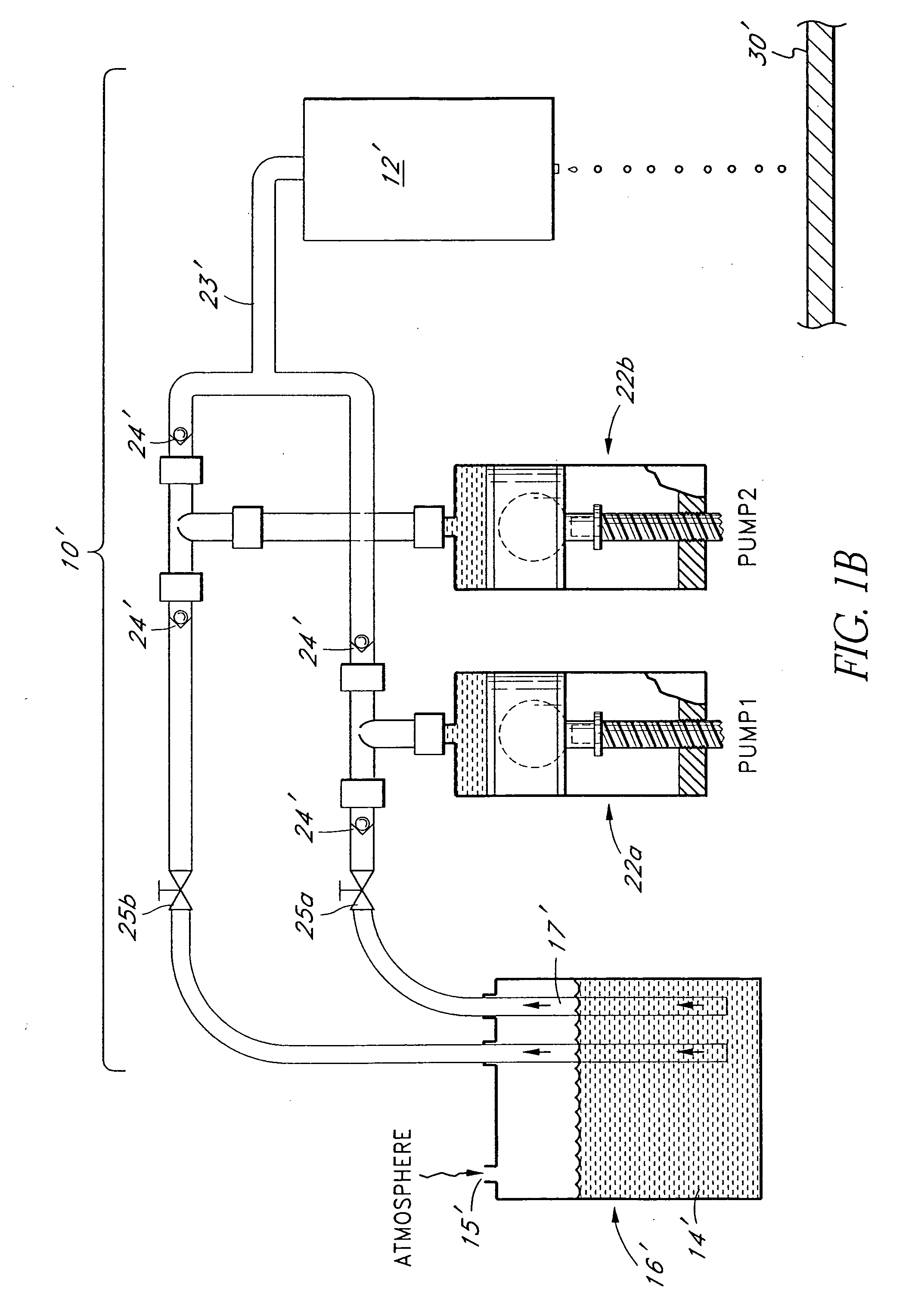
[0034]FIG. 1B is a schematic drawing of an alternative embodiment of a precision metered dispensing apparatus 10′ particularly adapted for continuous web production operation and having features in accordance with the present invention. For convenience of description and ease of understanding like reference numerals are used to refer to like components previously identified and described in FIG. 1A. The dispensing apparatus...


PUM

PropertyMeasurementUnit
Volumeaaaaaaaaaa
Volumeaaaaaaaaaa
Sizeaaaaaaaaaa

Abstract

A method and apparatus for dispensing precise quantities of reagents is disclosed including a positive displacement syringe pump in series with a dispenser, such as an aerosol dispenser or solenoid valve dispenser. The pump is controlled by a stepper motor or the like to provide an incremental quantity or continuous flow of reagent to the dispenser. The pump and dispenser are operated in cooperation with one another such that the quantity and/or flow rate of liquid dispensed by the dispenser can be precisely metered substantially independently of the particular operating parameters of said dispenser to attain a desired flow rate, droplet size or mist quality, droplet frequency and/or droplet velocity.

Description

RELATED APPLICATIONS [0001] This application is a divisional of U.S. application Ser. No. 10 / 459,381, filed Jun. 10, 2003, which is a continuation of U.S. application Ser. No. 09 / 286,154, filed Apr. 5, 1990, now U.S. Pat. No. 6,576,295, which is a divisional of U.S. application Ser. No. 08 / 899,325, filed Jul. 23, 1997, now U.S. Pat. No. 5,916,524, which reissued as U.S. application Ser. No. 09 / 897,788, filed Jun. 29, 2001, now U.S. Pat. No. RE38,281 E, which is a continuation-in-part of U.S. application Ser. No. 08 / 687,711, filed Jul. 26, 1996, now U.S. Pat. No. 5,738,728, U.S. application Ser. No. 08 / 686,957, filed Jul. 26, 1996, now U.S. Pat. No. 5,741,554 and U.S. application Ser. No. 08 / 687,712, filed Jul. 26, 1996, now U.S. Pat. No. 5,743,960. The entirety of each one of these prior applications is hereby incorporated by reference herein, and the priority of each of these prior applications is claimed in the present application.BACKGROUND OF THE INVENTION [0002] 1. Field of the...

Claims


Application Information

Patent Timeline
IPC IPC(8): B05D5/00B01L3/02G01N35/10
CPCB01L3/0265Y10T436/119163B01L2400/0415B01L2400/0487B01L2400/0633B01L2400/0666G01N35/1002G01N35/1009G01N35/1016G01N2035/1023G01N2035/1034G01N2035/1041Y10T436/2575Y10T436/112499B01L3/0268
Inventor TISONE, THOMAS C.
Owner BIODOT
Why Eureka
Try Eureka