Machine and methods for the manufacture of air-filled cushions

a technology of air-filled cushions and machines, which is applied in the field of air-filled cushion manufacture, can solve the problems of limited machine output rate, partially successful, and problems such as under and over inflation of cushions, and achieve the effect of simple air delivery and/or control system

Active Publication Date: 2006-12-28
PREGIS INNOVATIVE PACKAGING
View PDF42 Cites 46 Cited by
  • Summary
  • Abstract
  • Description
  • Claims
  • Application Information

AI Technical Summary

Benefits of technology

[0013] In further accordance with the invention, the injector has an inlet and an outlet and the drive mechanism is operative to move the plastic tubing over the outlet of the injector, whereby air can be injected through the injector into the plastic tubing. In this way, relatively low pressure air can be used, allowing for the use of a simpler air delivery and / or control system. Preferably the pressure is less than 5 psi, and most conveniently a pressure of 1-2 psi is used. The injector can be provided with a single outlet, but preferably has two or more outlets, arranged around its periphery, each outlet being operative to inflate a portion of the plastic tubing. Preferably the injector is provided with a cutter, upstream of the inlet, to cut a surface of the plastic tubing, allowing the plastic tubing to pass around the inlet.

Problems solved by technology

The throughput rate of the machines is therefore limited.
Various attempts have been made to develop a continuous process for filling air cushions, but have been only partially successful, problems being encountered in a number of areas.
The difficulty of injecting air into a moving cushion leads to problems with under and over inflation of the cushions.
One solution to this has been to inject air into the cushion using high pressure bursts of air, but this requires a high pressure air injection system and a complex control system.
An additional problem relates to the heat sealing mechanism.
When the machine must be stopped the heat sealer cools down, and when it is restarted the heat sealer takes a small amount of time to reach operating temperature, so that one or more air cushions can not be formed properly.
Moreover, further difficulties are encountered in conventional machines, including difficulty of machine set-up, particularly in drawing the tubing into and through the machine.

Method used


Image

  • Machine and methods for the manufacture of air-filled cushions
  • Machine and methods for the manufacture of air-filled cushions
  • Machine and methods for the manufacture of air-filled cushions

Examples


Embodiment Construction

[0029] Reference will now be made in detail to the present preferred embodiments of the invention, examples of which are illustrated in the accompanying drawings. The method and corresponding steps of the invention will be described in conjunction with the detailed description of the system.

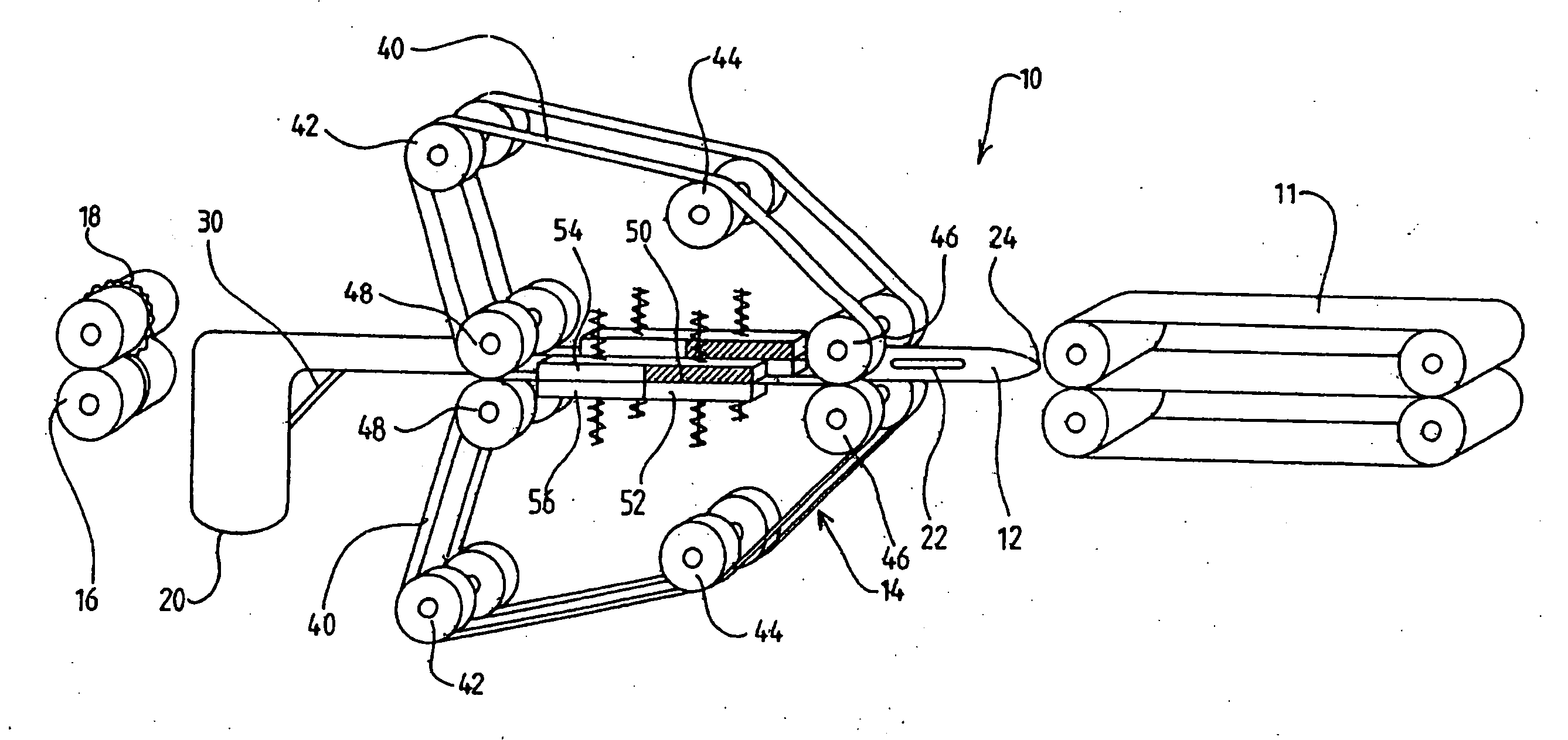
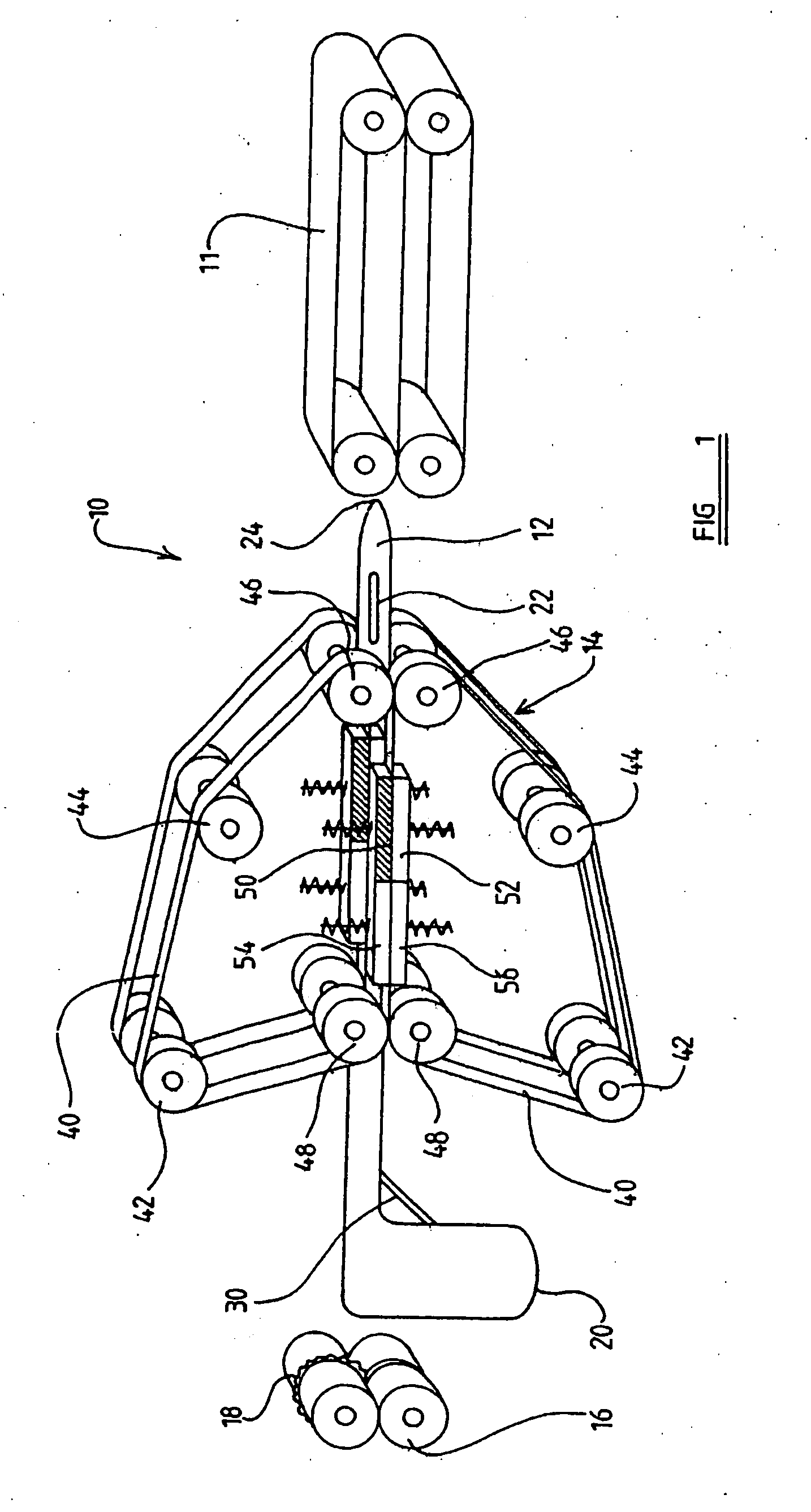
[0030] The methods and systems presented herein may be used for providing packaging cushions for cushioning articles during shipment. For purpose of explanation and illustration, and not limitation, an exemplary embodiment of the system in accordance with the invention is shown in FIG. 1 and is designated generally by reference character 10.

[0031] The internal components of a machine for the manufacture of gas-filled (preferably air-filled) cushions is illustrated in FIG. 1. The machine 10 comprises an air barrier 11, an injector 12, heat sealers 14, and pull rollers or drive rollers 16, which incorporate a perforator 18. These components of the machine 10 define a path along which tubular film...


PUM

PropertyMeasurementUnit
pressureaaaaaaaaaa
pressureaaaaaaaaaa
lengthaaaaaaaaaa

Abstract

A device and method are disclosed for forming air filled cushions. The device includes a drive mechanism to move inflatable tubing through the apparatus, and an injector, optionally including an outlet, located continuously within, or within a portion of, the tubing. This arrangement can permit the formation of air filled cushions in a continuous stream. Also disclosed is a roll of plastic tubing that is sealed transversely at a succession of intervals, with each pair of seals stopping just short of a longitudinal center line of the tubing. Such tubing might be used in conjunction with the apparatus, the central gap between the seals allowing passage of the injector.

Description

CROSS-REFERENCE TO RELATED APPLICATIONS [0001] This application claims the benefit of provisional application 60 / 589,748 filed Jul. 20, 2004, the entire content of which is expressly incorporated herein by reference thereto.BACKGROUND OF THE INVENTION [0002] 1. Field of the Invention [0003] This invention relates to improvements in the manufacture of air filled cushions. In particular, although not exclusively, this invention relates to air cushions of thin-walled plastic sheet, which can be used as infill or cushioning in the packaging and transportation of fragile articles. [0004] 2. Description of Related Art [0005] Conventionally, air filled cushions are manufactured from a roll of plastic tubing. A typical example of a method of manufacturing these cushions is described in International Patent Application WO 01 / 21391, incorporated by reference herein in its entirety. In this method the plastic tubing is drawn through the machine from a supply roll. The walls of the plastic tubi...

Claims


Application Information

Patent Timeline
Patent Type & Authority Applications(United States)
IPC IPC(8): B31B45/00A63B39/00B32B37/00B32B38/04
CPCB29C65/18Y10T156/1712B29C66/439B29C66/81465B29C66/83423B29C66/872B29C66/87443B31D5/0073B32B2553/023B65B1/02B31D2205/0023B31D2205/0047B31D2205/0052B31D2205/0082Y10T428/13Y10T156/1702Y10T156/12Y10T156/17Y10T156/1715B29C65/787B29C66/91431B29C66/91641B29C66/934B29C66/8161B29C66/8221B29C66/1122B65B1/04B65B41/12B65B51/30B65B61/02
Inventor GREENWOOD, JOHN STUARTPRICE, NEIL GLYNN
Owner PREGIS INNOVATIVE PACKAGING
Why Eureka
Try Eureka