RFID navigational system for robotic floor treater

Active Publication Date: 2006-12-28
SC JOHNSON & SON INC
View PDF31 Cites 141 Cited by
  • Summary
  • Abstract
  • Description
  • Claims
  • Application Information

AI Technical Summary

Benefits of technology

[0013] Thus, a consumer can mark a portion of a carpet or the like where there is a spot or extra soil by placing the RFID tag near it. This will cause the device to clean for a longer period near the tag. RFID tags could be permanently placed near entryways or high traffic areas that are typically more heavily soiled.
[0014] Alternatively, a consumer can place a different type of RFID tag adjacent a portion of the floor which is either too clean to need further treatment, or coated with fresh polish or othe

Problems solved by technology

This will cause the device to clean for a longer period near the tag.
(Typically small area rugs pose di

Method used


Image

  • RFID navigational system for robotic floor treater
  • RFID navigational system for robotic floor treater
  • RFID navigational system for robotic floor treater

Examples


Example

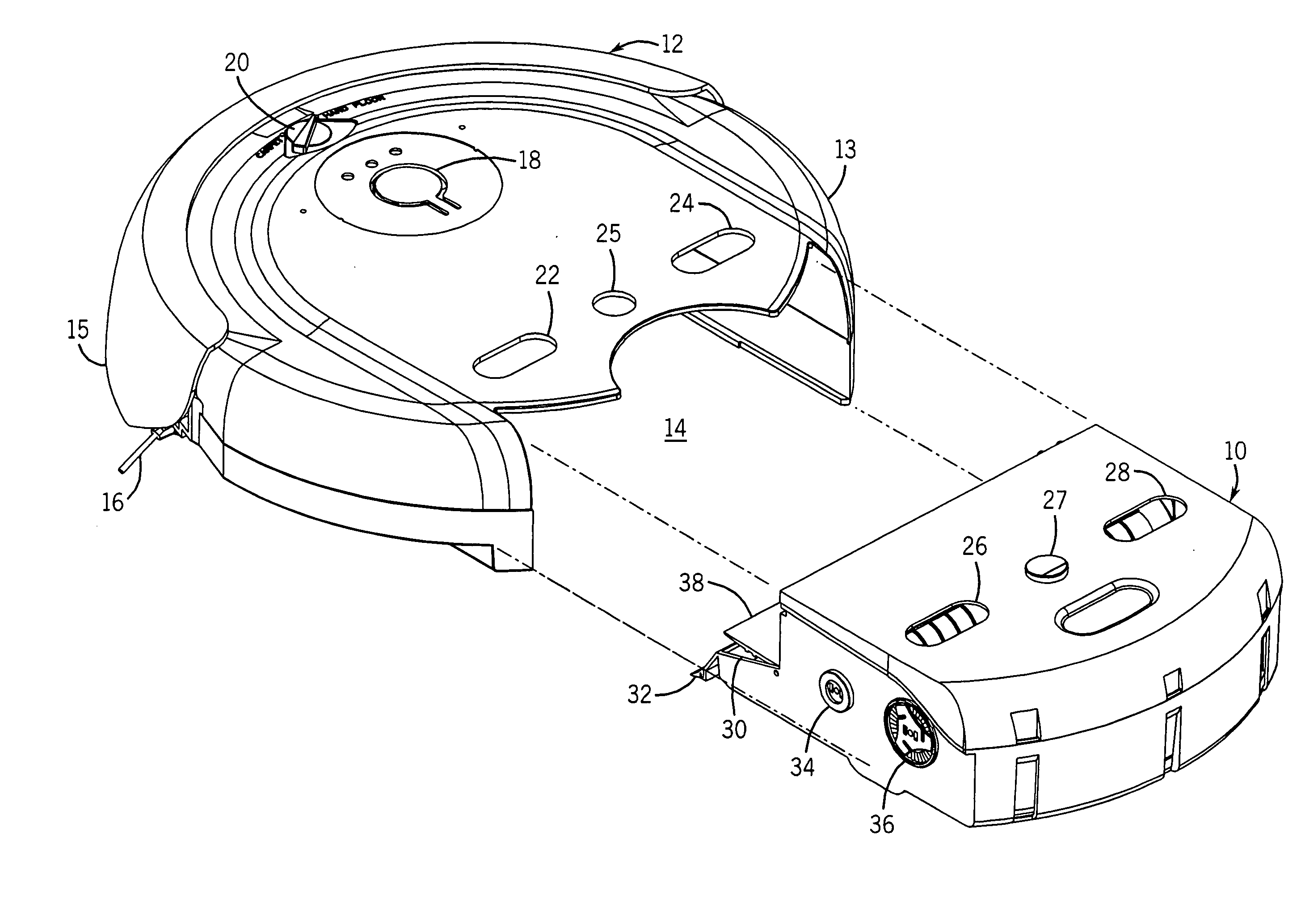
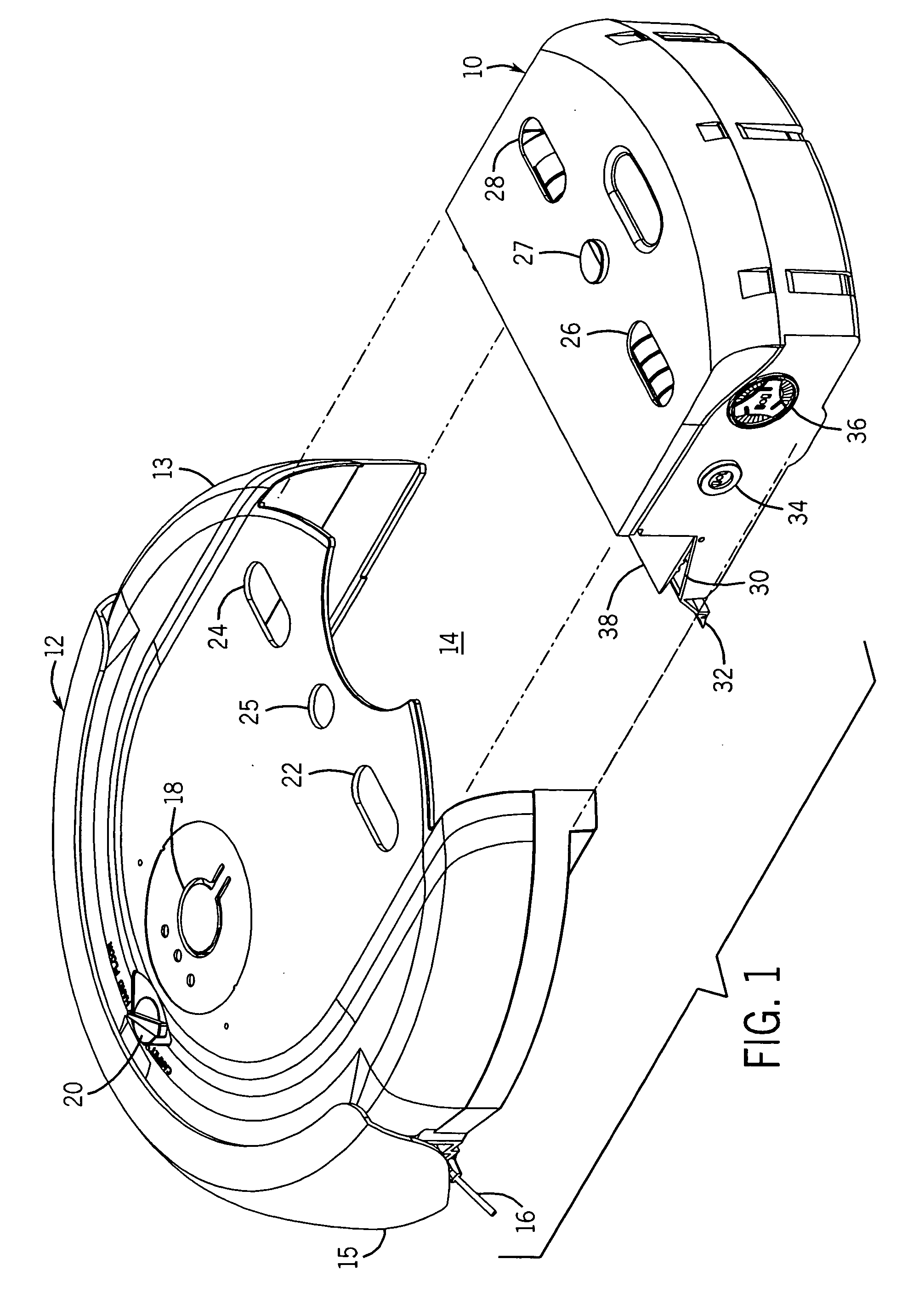
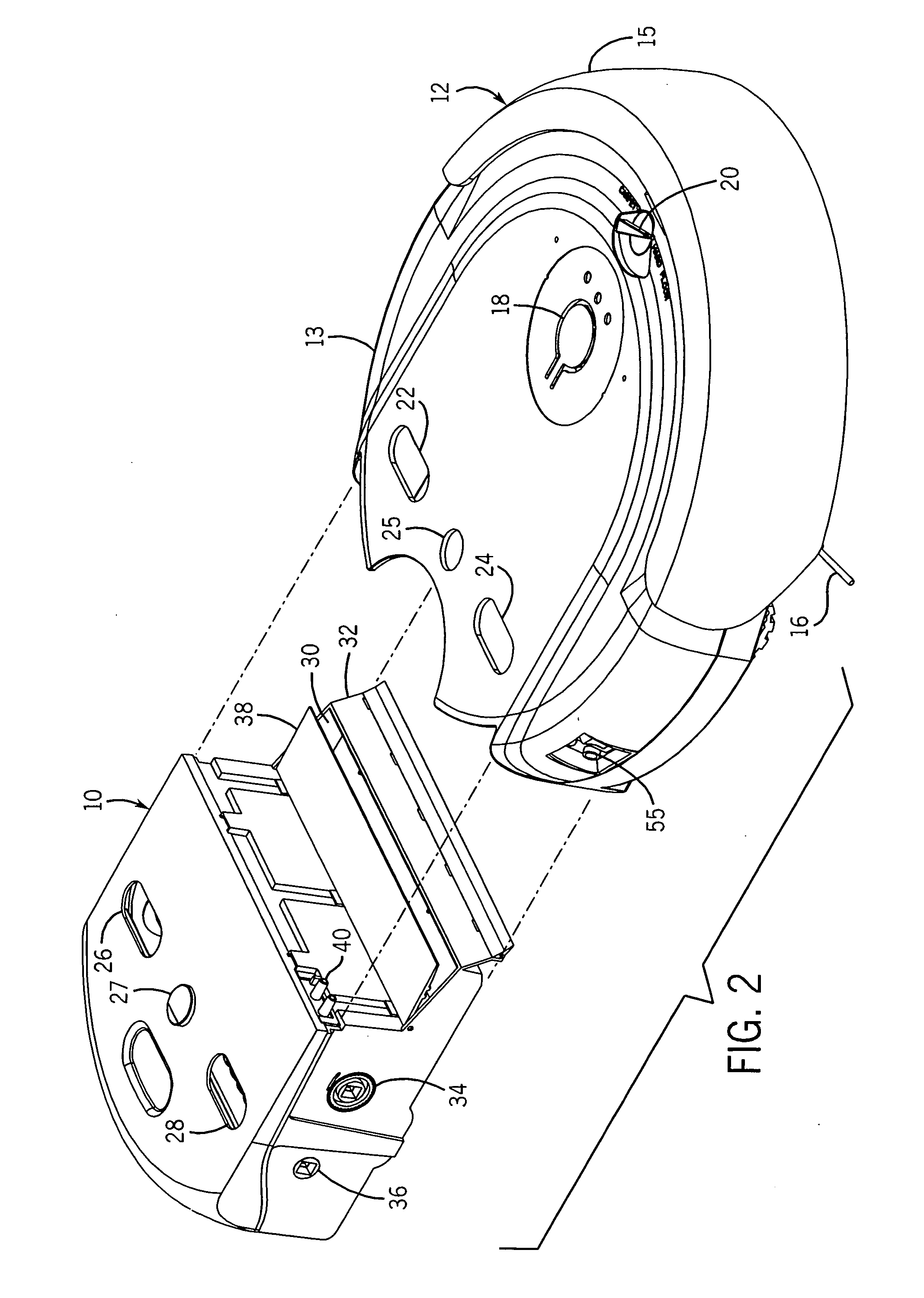
[0040] We first describe example autonomous cleaning devices with reference to FIGS. 1-11. This provides examples of environments where the invention of the present invention can be applied. Thereafter, we describe with reference to FIGS. 12-14 specific features of the present invention.

[0041] It should be understood that the present invention is also suitable for use with many other types of autonomous treating devices. Thus, the invention is not intended to be restricted to just cleaning devices, much less devices having the specific attributes shown in FIGS. 1-11.

[0042] Referring particularly to FIGS. 1 and 3, there is a cleaning cartridge 10 suitable to be inserted into a cleaning device 12. The cleaning cartridge 10 has a roll of sheet form cleaning cloth 44 which is provided in a reel-to-reel configuration. A portion of the roll is maintained in contact with the surface below the cleaning device 12 at any given time during operation. A motor 52 is provided in the cleaning de...


PUM


Abstract

Disclosed herein are navigational systems for automated robotic floor cleaners. RFID passive tags are positioned at specified areas of a floor to be treated so as to increase or decrease dwell time of the cleaning device adjacent the tags. An RFID interrogator on the robot learns from each tag its nature, and based thereon instructs the device to change the dwell time over specified areas. This permits areas of a carpet or other surface requiring extra or less treatment to be cleaned in an optimal manner.

Description

CROSS-REFERENCE TO RELATED APPLICATIONS [0001] Not applicable STATEMENT REGARDING FEDERALLY SPONSORED RESEARCH / DEVELOPMENT [0002] Not applicable BACKGROUND OF THE INVENTION [0003] It is desirable to minimize the amount of human labor expended in maintaining and cleaning buildings. The art has therefore developed autonomous robotic devices that can clean or otherwise maintain or treat hard floors, carpeting and similar surfaces without the necessity for a human to be present during the operation of the device. [0004] Such robotic devices typically have a programmable controller for directing the device in a preferred movement pattern. The controller is linked to motors that drive the wheels of the device. Many of these devices also include sensors to detect positions of the device relative to a pre-set path or relative to an obstacle such as a wall or a staircase. Other of these devices include programming to provide for a pre-set navigational path, and sensors to detect the presence...

Claims


Application Information

Patent Timeline
IPC IPC(8): G06F19/00
CPCG05D1/0227G05D2201/0203G05D1/0261
Inventor HARWIG, JEFFREY L.JAWORSKI, THOMASSAWALSKI, MICHAEL M.YEUNG, DIK MANSU, DRAGON
Owner SC JOHNSON & SON INC
Why Eureka
Try Eureka