Twist bit for drilling mortar and for optimizing dissipation of heat and dust created by the drilling

a technology of drilling mortar and drilling hammer, which is applied in the direction of turning machine accessories, twist drills, manufacturing tools, etc., can solve the problems of not being suitable for the purposes, and achieve the effect of optimizing the dissipation of heat and dus

Inactive Publication Date: 2007-01-04
SWITZER BRUCE D
View PDF13 Cites 24 Cited by
  • Summary
  • Abstract
  • Description
  • Claims
  • Application Information

AI Technical Summary

Benefits of technology

[0011] ACCORDINGLY, AN OBJECT of the present invention is to provide a twist bit for drilling mortar and for o

Problems solved by technology

Furthermore, even though these innovations may be suitable for the specific individual purposes to which they

Method used


Image

  • Twist bit for drilling mortar and for optimizing dissipation of heat and dust created by the drilling
  • Twist bit for drilling mortar and for optimizing dissipation of heat and dust created by the drilling

Examples


Embodiment Construction

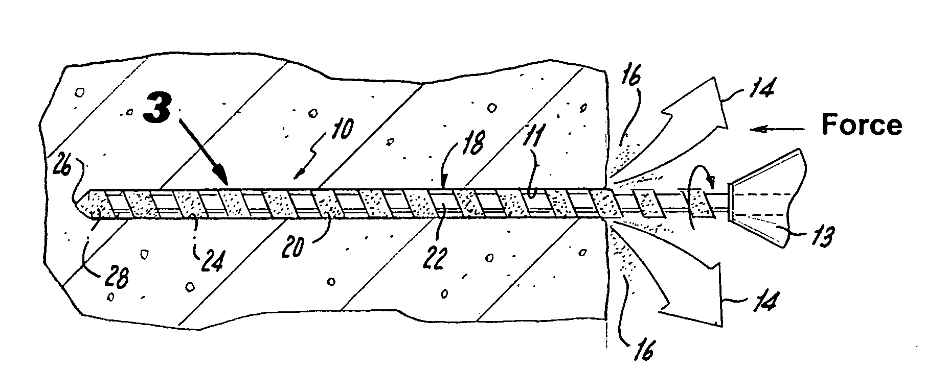
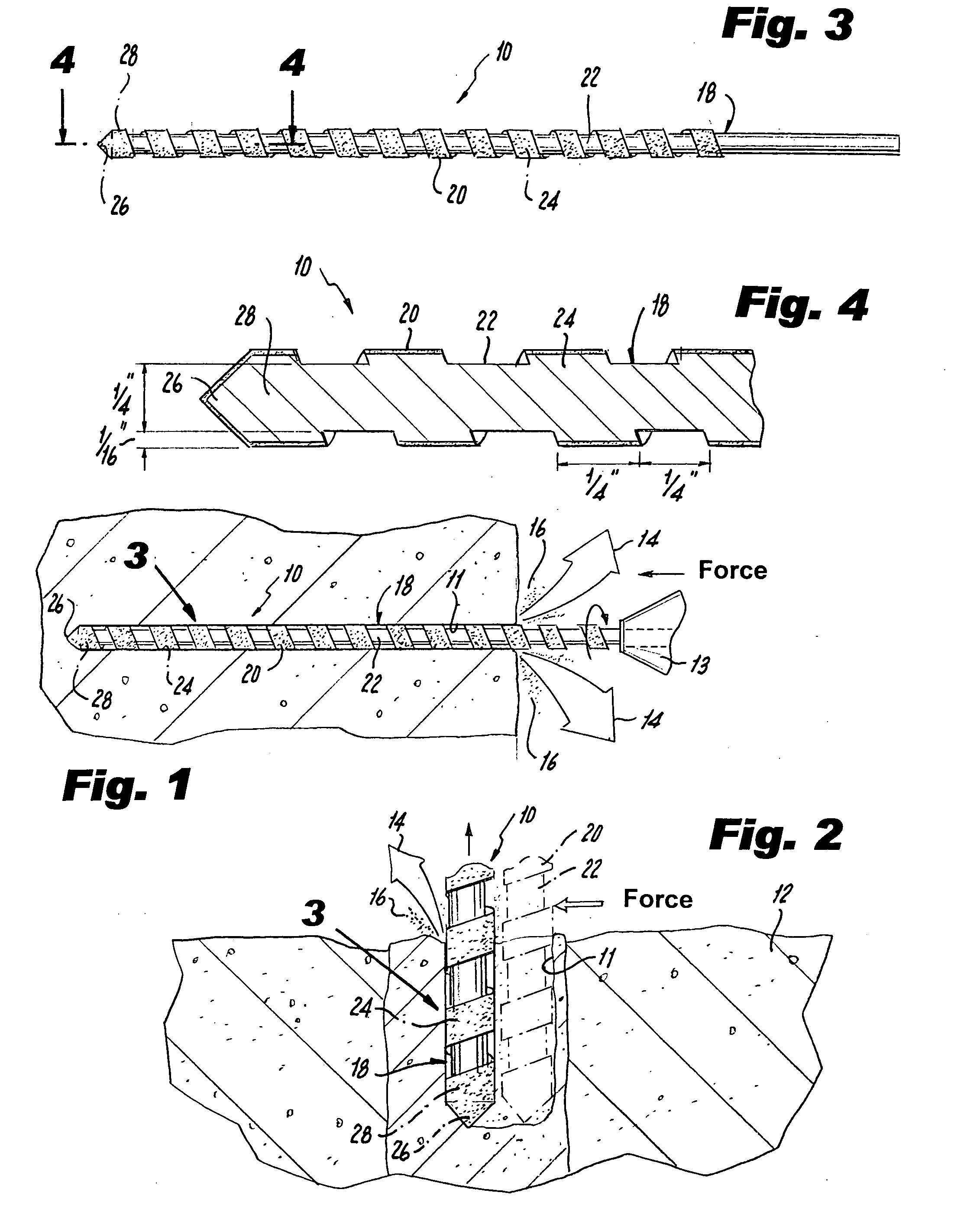
[0032] Referring now to the figures, in which like numerals indicate like parts, and particularly to FIGS. 1 and 2, which are, respectively, a diagrammatic cross sectional view through the mortar showing the twist bit of the present invention drilling an axial hole in the mortar and optimizing dissipation of heat and dust created by the drilling, and, a diagrammatic cross sectional view through the mortar showing the twist bit of the present invention drilling and cutting a lateral hole in the mortar and optimizing dissipation of heat and dust created by the drilling, the twist bit of the present invention is shown generally at 10 for drilling holes 11 in mortar 12 via a drill motor 13 and for optimizing dissipation of heat 14 and dust 16 from the hole 11 created by the drilling.

[0033] The configuration of the twist bit 10 can best be seen in FIGS. 3 and 4, which are, respectively, a diagrammatic side elevational view of the twist bit of the present invention identified by ARROW 3 ...


PUM

PropertyMeasurementUnit
Widthaaaaaaaaaa
Heightaaaaaaaaaa

Abstract

A twist bit for drilling mortar and for optimizing dissipation of heat and dust created by the drilling. A shaft has a flute therein configured in a spiral configuration therealong leaving a flute land thereon also configured in a spiral configuration therealong, a tip, and a head including the tip and a portion of the flute land coextensive with the tip. Diamond dust is disposed only on the flute land and the head. To optimize the dissipation of the heat and the dust created by the drilling, the twist drill operates via a drill motor in a range of approximately 25,000 RPMs to approximately 26,000 RPMs. The flute has a width of approximately ¼″ and the flute land has a width of approximately ¼″ and a height of approximately 1/16″.

Description

BACKGROUND OF THE INVENTION [0001] 1. Field of the Invention: [0002] The present invention relates to a twist bit for drilling mortar, a and more particularly, the present invention relates to a twist bit for drilling mortar and for optimizing dissipation of heat and dust created by the drilling. [0003] 2. Description of the Prior Art: [0004] Numerous innovations for drill bits have been provided in the prior art that will be described. Even though these innovations may be suitable for the specific individual purposes to which they address, however, they differ from the present invention. [0005] A FIRST EXAMPLE, U.S. Pat. No. 3,692,127, Issued on Sep. 19, 1972, to Hampe et al. teaches an improved rotary diamond core bit offering longer life in dry and in chip flush drilling. Grade AAAA dodecahedron diamonds within the range of 18 to 22 diamonds per carat size, each having a select rectangular pyramid point region free of internal flaws and with an included angle of 100 degrees to 12...

Claims


Application Information

Patent Timeline
IPC IPC(8): E21B10/44
CPCB23B51/02B23B2226/315B23B2226/75B28D1/146B23B2251/44B23B2270/56B23B2251/406
Inventor SWITZER, BRUCE D.
Owner SWITZER BRUCE D
Why Eureka
Try Eureka